Often, you will use a key, button, or switch to obtain your project's input values. In addition, to interface a key or switch to a microcontroller, you require a single GPIO pin. The problem arises when you need to interface numerous keys such as 12 or more. Since the Microcontroller will need many GPIO pins and you will most likely lose most of the pins in the process. A 4×4 keypad quickly solves the above problem. But what exactly is a 4×4 matrix keypad? How does it work? This article answers all the above questions and more.
Contents
- What is a 4×4 Keypad?
- 4×4 Keypad Module Pin Configuration
- Rows
- Columns
- 4×4 Keypad Module Features and Specifications
- Specifications
- Features
- How the 4×4 Matrix Keypad Module Works
- How Microcontroller Scans lines for a Button Pressed State
- How to interface 4×3 & 4×4 Membrane Keypad with Arduino?
- Linking the 4×3 and 4×4 keypads to Arduino
- Procedure
- 4×4 Keypad: Installing the Library
- 4×4 Keypad: Arduino Code
- 4×4 Keypad: Link the LCD to the Keypad
- 4×4 Keypad: Applications
- Conclusion
What is a 4×4 Keypad?
The 4×4 matrix keypad is a loading or input device mainly used to provide a project's input values.
Note that a 4×4 matrix membrane keypad has 16 parallel keys and allows for 16 input values.
What makes the 4×4 Keypad exceptional is that it only uses 8 GPIO microcontroller pins.
As earlier stated, if you were to interface 16keys, you would require 17 input pins for them to work effectively.
However, you will only use eight microcontroller pins to read through the pad with a matrix order.
4×4 Keypad Module Pin Configuration
Rows
| Pin Name | Pin Number | Interpretation |
| R1 | 1 | Removed from 1st row |
| R2 | 2 | Removed from 2nd row |
| R3 | 3 | Removed from 3rd row |
| R4 | 4 | Removed from 4th row |
Columns
| Pin Name | Pin Number | Interpretation |
| C1 | 5 | Removed from 1st column |
| C2 | 6 | Removed from 2nd column |
| C3 | 7 | Removed from 3rd column |
| C4 | 8 | Removed from 4th column |
4×4 Keypad Module Features and Specifications
Specifications
| Variable | Value |
| Design | Ultra-thin |
| Cable measurement | 2.0cm ×8.8cm |
| Keypad measurement | 6.9cm ×7.9cm |
| Number of pins | 8 |
| Highest voltage rating | 24V DC |
| Highest current rating | 30mA |
| Range of operating temperature | *30 to 122 F/ 0 to 50 C |
| Product model | 4×4 Keypad Module |
Features
- Long-lasting
- Adhesive backing
- Simple interface
Special Offer: Get $100 off your order!
Please email [email protected] for details.
How the 4×4 Matrix Keypad Module Works
Keypad modules have buttons laid out in rows and columns. A 4×4 keypad module has four rows and, likewise, four columns.
On the other hand, a 3×4 keypad module has four rows and three columns.
All the switches on a row link to all the other buttons in the same row through the conductive trace found under the pad.
Similarly, all the switches on the column link to buttons on the same column through the conductive path.
All the rows and columns are connected to one pin hence eight pins on a 4×4 keypad module. Plus, underneath all the keys, there is a membrane switch.
Therefore, when you press a button, it shuts the switch in the middle of a row and a column trace, enabling current flow in the center of a row and column pin.
The Arduino knows which button you pressed by finding the column and row pin linked to that button.
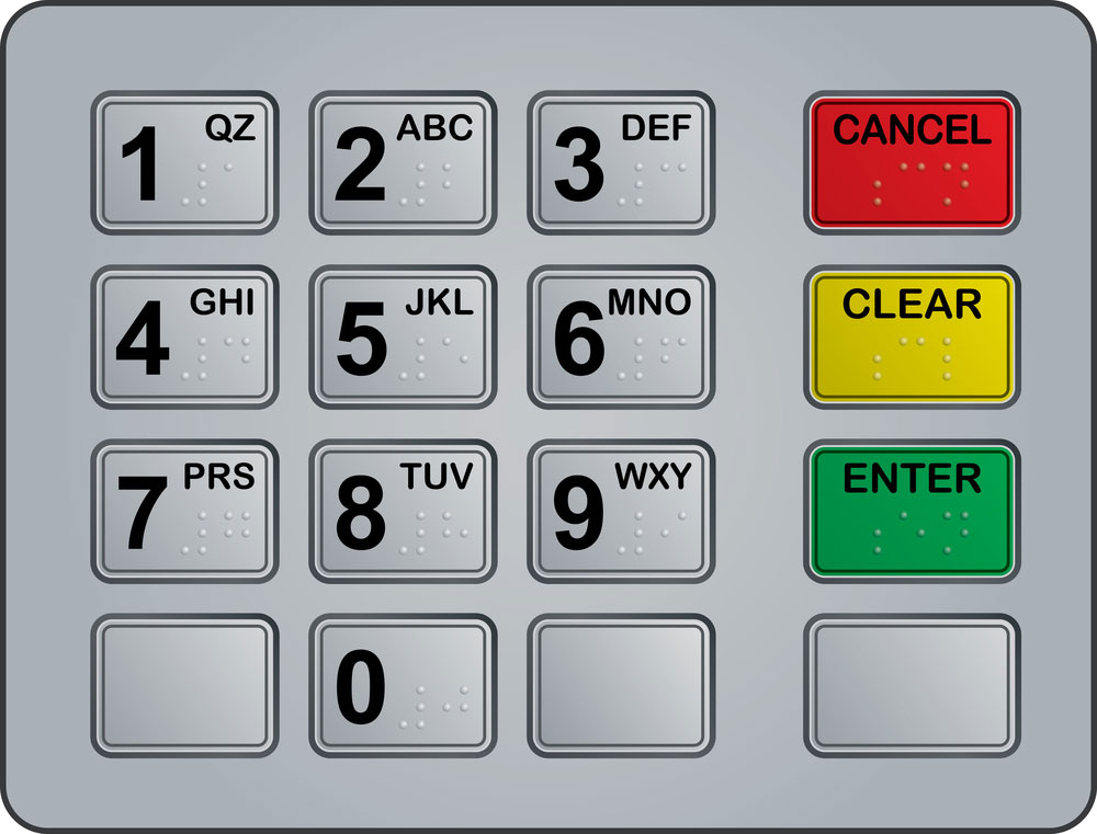
ATM keypad
First, the Microcontroller sets every row and column line to input.
Next, the Microcontroller sets one row to LOW.
After which, it starts going through the column lines one by one.
A computer microcontroller
Provided the column connections remain high throughout the inspection, that means that no button on that row is pressed.
However, when one of the column connections goes low, the Microcontroller remembers which row was previously LOW and which column was also LOW.
Finally, the Microcontroller knows the button pressed with the identified column and row.
How to interface 4×3 & 4×4 Membrane Keypad with Arduino?
Linking the 4×3 and 4×4 keypads to Arduino
Start by attaching pin 1 of the Keypad to pin 9 of the Arduino.
Follow the same process for the rest of the pins going leftwards, like 3 to 7, 4 to 6, etc.
Below are diagrams you can follow for direction whether you are connecting a 4×3 or a 4×4 keypad.

4×3 and 4×4 keypads linked to Arduino
Source: Circuit Basics
Locating your Keypads Pinout
If you have a keypad whose pin layout isn't similar to the ones shown above, you will have first to check the pins to know their layout.
You can make a test circuit simply by linking a current limiting resistor and an LED to the Arduino, as shown below.

Arduino Linked to a current limiting resistor
Source: Circuit Basics
Procedure
Firstly, you must find the keypad pins linked to buttons on the rows. So place the black wire in the first left pin.
Randomly press a button in the first row while inserting the red (positive) wire inside the remaining pins.
If the light-emitting diode lights up when you insert the ground wire, thrust the wire again into all the remaining pins.
When the LED flashes in an unrelated pin, the ground pin links to the nail on the first row.
However, when no buttons ignite, the LEDs glow, meaning the black wire and the first row are not connected.
Now place the black wire (ground) in the adjacent pin. Then randomly push a button on another row then replicate the above procedure until you have identified pins for all the rows.
Secondly, to identify which columns the pins are linked to, place the black wire in the plug marked as row 1. Then randomly press any button on that row.
After which, place the red wire (positive) in all the other pins. The pin connected to the button you pressed will make the LED glow.
Next, randomly push a button in the identical row and lodge the red wire into the remaining pins. Repeat the process for all the columns.
4×4 Keypad: Installing the Library
To install, scroll to Sketch, tap Include Library, click on Manage libraries, then wait as the library manager downloads the libraries index.
4×4 Keypad: Arduino Code
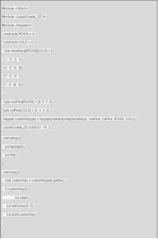
Once you have successfully installed the library, you can now upload the code below on the Arduino for a 4×4 keypad.
4×4 keypad Arduino Code

4×3 Keypad Arduino Code

From the above code, lines:
3 to 4 determine the columns and rows on a membrane keypad.
6 to 11 define the character printed when you press a specific button on your Keypad.
Please note the code prints characters in the exact order represented on a keypad.
Nevertheless, if the membrane keypad you are using differs from those above, you can determine the characters printed after pushing a button.
Immediately upload the code and randomly push a key on the serial board; the values will appear as outlined below.
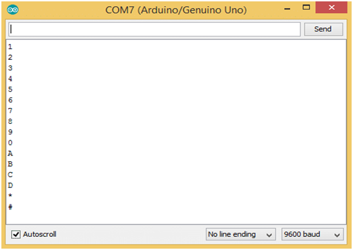
Values on a serial board
Source: Circuit basics
4×4 Keypad: Link the LCD to the Keypad
First, attach the LCD Vcc and ground pins on the Arduino, after which you interlink the LCD pins for various Arduino boards as shown below.
| SDA pin | SCL pin | Arduino |
| A4 | A5 | Uno |
| A4 | A5 | Nano |
| A4 | A5 | Mini |
| A4 | A5 | 101 |
After linking, attach the Arduino to the Keypad the upload the code:
Once you complete all the required connections, your design should somewhat resemble:

Keypad connected to Arduino and LCD screen
Source: Circuit Basics
4×4 Keypad: Applications
- Engineering Systems
- Alarm systems
- Vending machines
- Measuring instruments
- Embedded systems data entry
- Recreational Projects
Conclusion
By now, you should be able to interface a keypad membrane with an Arduino properly. It may be challenging at first, but you will indeed manage after a couple of trials.
Above all, remember to enter the codes correctly since they will make or break your project's performance. If you need more help, feel free to contact us.
Special Offer: Get $100 off your order!
Please email [email protected] for details.