


Semiconductors and integrated circuits need electrical interconnections with their packaging during device fabrication. This interconnection also applies to connecting two printed circuit boards or ICs to other electronics.
Wire bonding is the most affordable and flexible connection technology for all these interconnections. Additionally, it can work at frequencies above 100 GHz. Therefore, using it in your project makes sense if you require such interconnections. We have looked at the technology in detail below, so take a look!
Contents
Special Offer: Get $100 off your order!
Please email [email protected] for details.
What is Wire Bonding?
Wire bonding is a solid phase welding process that joins a wire and pad surface (two metallic materials). The electrical interconnection technique uses a thin wire plus ultrasonic energy, pressure, and (or without) heat. It combines these to create intimate contact between the two materials.
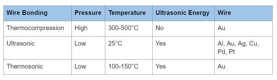
Types of Wire Bonding
- Thermocompression Bonding: This process uses force, heat, and time to weld the two materials via inter-diffusion. The wire (heated in some cases) gets pressed against a hot surface (150°C or more). It occurs at high pressure for a limited period. But the process uses no friction and only works on a gold wire and a gold bond surface.
- Ultrasonic Bonding: This requires pressure, ultrasonics, and time to weld the two materials. The process involves pressing the wire against the surface at ambient temperature. Additionally, it should be at a low force with vibration for a limited period to create the bond. You can use this method with aluminum, gold, silver, palladium, copper, or platinum (wire or ribbons). It has two forms: wedge and peg bonding.
- Thermosonic Bonding: This bonding process uses force (pressure), heat, ultrasonics, and time to weld two materials. It should occur at low pressure and undergo vibration for a limited period to create the bond. Usually heated in some cases, the wire gets pressed on the hot surface (150°C or less). But like thermocompression bonding, the process only works with gold wire and a gold bonding surface. However, it has three forms: gold ball bonding, wedge bonding, and stud bumping (bump bonding).
Special Offer: Get $100 off your order!
Please email [email protected] for details.
Wire Bonding Forms
The following are the two primary wire bonding forms:
Ball Bonding
In ball bonding, the wire passes through a hollow capillary. After that, an EFO (Electronic Flame-Off) system melts the small portion extending outside. The surface tension of the molten wire forms a ball before the wire solidifies. Next, it gets pressed to the pad using sufficient force to cause plastic deformation. The result is an intimate bond with the bond pad surface.
Wedge Bonding
With wedge bonding, the capillary's bottom side squeezes the wire tab to the bonding pad at a 30-60° angle. After that, ultrasonic energy shapes the bond between the place and the wire. The capillary then moves to the second bond area and repeats the above process. After linking the two sections, the wire gets clipped and snapped.
Wire Bonding Materials
The most commonly used materials for bonding wires are:
Gold Wire
Gold wire is the preferred material in thermosonic and thermocompression gold wire bonding. But the material must be clean and have a smooth surface finish to ensure sufficient adhesion and no clogging along the capillary chamfer diameter.
However, ultra-pure gold is very soft. Therefore, small quantities of beryllium (5-10 ppm) or copper (30-100 ppm) get added to make the material workable. The former is stronger than the latter by 10-20%. Thus, it is ideal for masonic bonding (automated) because the quick capillary movements stress the wire.
Aluminum Wire
Like gold, pure aluminum is too soft to make a reliable wire. Therefore, the material gets alloyed using 1% silicon or magnesium for strengthening purposes. Aluminum with 1% magnesium is superior to silicon alloy wire because it exhibits fatigue and strength degradation resistance after exposure to high temperatures. But Aluminum-silicon is stronger at room temperature and forms a more robust joint with the aluminum bond pad.
Copper Wire
Copper wire to bond pad metallization has become popular due to its affordability and sweep resistance during plastic encapsulation. However, copper is more rigid than gold and aluminum, which can push the bond pad metallization aside. Also, the material oxidizes quickly, so you must carry out copper ball bonding in inert atmospheres.
Wire Bonding Guideline
Developing wire bonds requires the following guidelines.
Process Optimization
Process optimization is essential when developing and improving production. The production process is usually a continuous loop that includes four steps: design & development, characterization, control, and optimization. Process characterization and control stages are in a constant loop in the middle. Meanwhile, optimization loops around the entire production process to improve each step.
The design and development stage usually includes the achievable goals and information required to set up the wire bonds mechanism. After that, characterization covers categorizing wire bonding failure data, such as wire breaking and bond off-center. Thirdly, control focuses on stabilization performance by regulating bonding parameters, bond-tool installation, wire pulling steps, etc.
Optimization focuses on improving all these steps to make the bonding process more efficient and reliable.
Wire Bonding Design
The design of a wire bonding mechanism should prevent failures associated with vibration fatigue, noise, wire flexure fatigue, interdiffusion, etc. Some inputs for this design process include the following:
- Chip thickness and material
- Bond pad thickness, material, pitch, etc.
- Transistor conduction channel resistance
- Output capacitive load (designed-for)
- Max allowable interconnect resistance/length (wire diameter)
- And more
Bond Evaluation
Bond evaluation occurs after the bonding process is complete. It can be a visual evaluation or a mechanical test of the bond patterns. The former involves evaluation using scanning electron microscopes, optical microscopes, and other similar instruments. On the other hand, automated testing involves using methods listed in the MIL-STD-883: test method standard. They include the following:
- Delay measurements
- Ball bond shear test
- Random vibration
- Internal visual
- Stabilization bake
- And more
Failure Mechanisms of Wire Bonds
A manual or commercial wire bonder can create imperfect wires with weak internal structures. Some typical failures include the following:
- Cratering: Usually caused by over bonding. The damage occurs under the bond pad but can leave a hole in the substrate. Also, it can leave a divot fixated on the wire in severe cases.
- Wirebond fracture/lifting: Lifting is when ball bonds detach from the silicon tabs or chips. Also, it refers to the ball bond not sticking to the bond pad.
- Inconsistent tails: These failures can cause shorting with other traces, bonds, or bondable surfaces nearby.
- Improper positioning: This issue can lead to bad welds from the bond head or shorts.
- Poor welding: Creates weak gold, aluminum, or copper ball bonding.
Pad cleanliness can help eliminate some of these faults, while failure shooting using a fishbone diameter can help isolate any arising issues when wire bonding.
Summary
As you can see, wire bonding is critical in making electrical interconnections for ICs or other semiconductor devices. The process can have failures, but you can minimize these by following the guidelines and using the appropriate material. If you have any questions, contact us for more details.
Special Offer: Get $100 off your order!
Please email [email protected] for details.


