TB6612FRNG arduino module makes it easy to control the speed of a DC motor using an Arduino. If you control the motor directly with an Arduino, you will run into challenges and may buy another component. The output pins of an Arduino cannot supply enough current to components such as DC motors.
Therefore, most technological enthusiasts interface Arduino and DC motors using an H-bridge, the TB6612FRNG. While these components are easy to interface with, TB6612FRNG Arduino projects can present challenges. Here at OurPCB, we provide you with all the needed information.
Contents
Special Offer: Get $100 off your order!
Please email [email protected] for details.
TB6612FRNG Specifications
At the core of the dual TB6612FRNG are MOSFETs, making it efficient and small. Typically, manufacturers use bipolar junction transistors or MOSFETs to produce H-bridges. H-bridges designed using MOSFETs have no voltage drop, unlike the operation of BJTs.
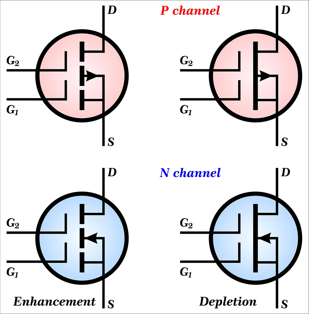
(MOSFETs)
A Bridge with BJTs has a total drop of 1.4 volts because the current has to go through two BJTs. In low voltages, such drops amount to a large percentage of the supply voltage.
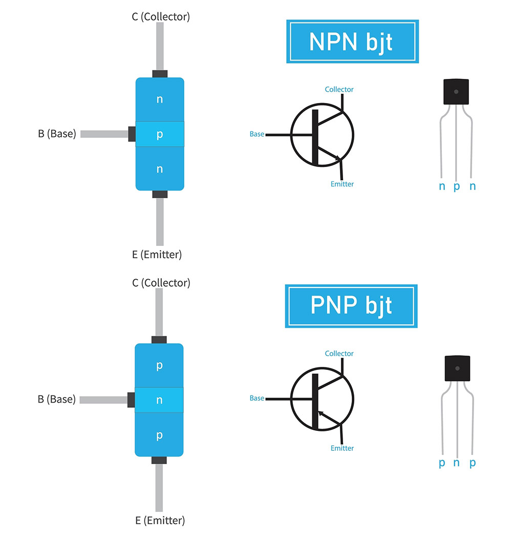
(Bipolar Junction Transistor, BJT)
The resistance depends on the operation mode when an H-bridge has MOSFETs. When the channel is open, there is a negligible voltage drop on the bridge. Consequently, the motor utilizes most of the power. TB6612FRNG does not require heat sinks because there is negligible power dissipated as heat.
Some of the specifications of TB6612FRNG include
- A standby power mode
- 1.2 A output current (3.2 A peak current)
- 2.5-13.5V motor power supply
- 2.7-5.5V Logic supply voltage
- Internal thermal shutdown
Special Offer: Get $100 off your order!
Please email [email protected] for details.
Pin Layout of a Dual TB6612FRNG Module
The TB6612FRNG module has input pins and output pins aligned on different sides.
The module has 16 pins which include:
- Three ground pins
- 2 PWM pins (PWM A and PWM B for controlling two motors)
- VM- Motor Voltage
- VCC- Power Supply
- STBY- activates standby mode when set to HIGH
- A1 and A2 ("+" and '-') for Motor A
- B1 and B2 ("+" and '-') for Motor B
- AIN1 and AIN2 (control signals for motor A)
- BIN1 and BIN2 (control signals for motor B)
How to control TB6612FRNG
The TB6612FRNG is a dual-motor driver, as indicated in the pin layout. For your information, the module has a single-chip timer that generates PWM outputs.
AIN1, AIN2, BIN1, and BIN2 receive control signals to TB6612FRNG from a controller such as Arduino. The timer outputs hardware PWM, allowing the controller to only engage in calculations.
When the PWM changes its duty cycle, the PWM hardware reduces the PWM software burden. Pins STBY, PWM1, and PWM2 control the motor's speed, braking, and stopping. Typically, the TB6612FRNG circuit has a 10µF capacitor that filters the power supply and can withstand 25V.
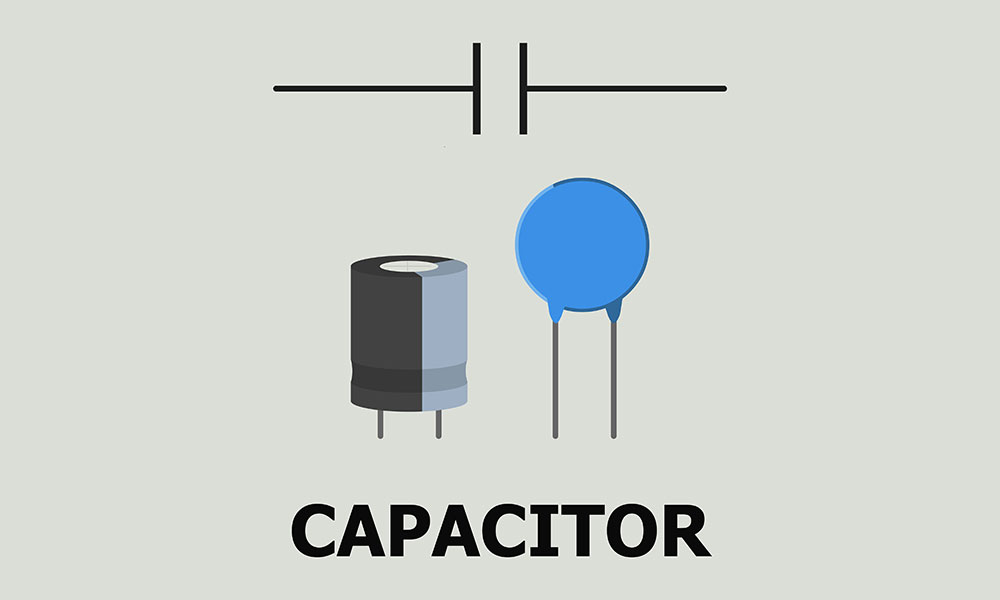
(Capacitor)
The TB6612FRNG can be operated in four modes.
- Stop
- Short Brake
- Clockwise (Forward)
- Counterclockwise (Reverse)
Each of the above modes depends on which of the pins of the TB6612FRNG you activate. The following table shows how you achieve different modes of operation.
| Operation (mode) | AIN1/ BIN1 | AIN2/BIN2 |
| Forward (Clockwise) | High | Low |
| Reverse (Counter-clockwise) | Low | High |
| Stop | Low | Low |
| Sort Brake | High | High |
You can use the PMA and PWMB to control the speed of a DC motor. These two pins use pulse modulation, a concept of regulating the average voltage.
How to connect TB6612FRNG with Arduino
TB6612FRNG provides an easy and inexpensive alternative to controlling DC motors. On your desk, you can start, stop and vary the speed of a motor using TB6612FRNG. Two standard H bridges inside the TB6612FRNG enable the motor control process.
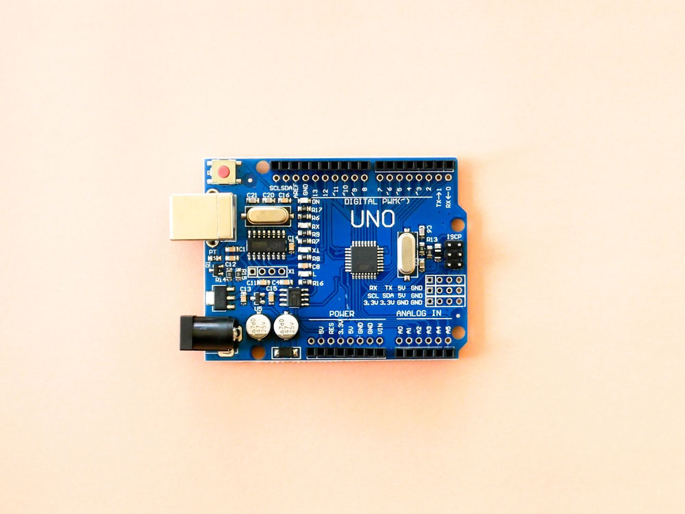
(Arduino Uno R3)
Before connecting the TB6612FRNG to the Arduino, it is essential to identify the pins and their respective purpose. The Arduino and the TB6612FRNG have inputs, outputs, and power pins, which are labeled. Therefore, you can use a manual to avoid confusion on the pin layout. The connection of the circuit should be according to the following steps.
Step 1 Required parts
- Sparkfun motor driver 1A Dual TB6612FRNG
- Two DC motors; not exceeding 9v and 1.2 current ratings
- 1 Arduino Uno R3
- One breadboard
- 6V DC power supply (Battery)
- 9V Dc motor supply (Battery)
Tools
- Soldering gun
- Wire stripers
Step 2 soldering the connections
The circuit will work better if some parts are soldered. The TB6612FRNG has no pin headers; hence you will have to solder them. Soldering shouldn't be a challenge when you are using header pins. Break into sets of 8 header pins and place them on the breadboard.
On top of them, place the TB6612FRNG ensuring a tight angle between the pins and the TB6612FRNG before soldering. Use a little solder iron on each pin to ensure a clean soldering exercise.
Moreover, you will solder jumper wires to the battery terminals and make them easy to use with the breadboard.
Step 3 Wiring it up
The 9V Battery will supply the Arduino, while the motors will run on 6V Battery. Place the TB6612FRNG in the middle of the breadboard to have pin rows on each side, and one side is the input while the other is the output.
The breadboard has two power rails. Here, we’ll use one to power the Arduino and the TB6612FRNG and the other to power the motors. The two sources' grounds are connected to ensure the circuit has a common ground.
Each motor has three connection points; LN1 and LN2 control the direction, while the PM controls the speed. STBY puts the motors to sleep or brings them ON.
(DC motor)
Connect and match Arduino pins with the TB6612FRNG pins, as shown
- Pin 3-PMWA
- PIN 8-AIN2
- PIN9-AIN1
- PIN10-STBY
- PIN11-BIN1
- PIN12-BIN2
- PIN5-PWMB
Connect the two motors' A01, A02, BO1, and BO2, and match them to the breadboard.
Back EMF protection
When you supply the motor with power, it rotates and has inertia. If you cut off the power, the motor keeps spinning, acting as a generator. As a result, it supplies current back to the circuit. Using a diode in this simple circuit, we can protect the components against back EMF.
In this circuit, the motors have little inertia, and the back EMF is negligible.
Step 4: Library and Code
Once you have set up the hardware as directed, the final phase is compiling and uploading the Arduino IDE code. First, you need to download and install the right set of libraries. You can check out this tutorial on how to install libraries in Arduino. Follow all the steps, and your setup will be ready to run in minutes.
Conclusion
Generally, the TB6612FRNG has provided opportunities for many technology enthusiasts struggling in class and personal projects. In this article, we learned how we could start, stop or vary the speed of a dc motor. There is an unlimited number of projects where you can implement DC motors.
You can implement this simple project in the context of complex projects. If you need more information, contact us.
Special Offer: Get $100 off your order!
Please email [email protected] for details.