One device that has played a critical role in developing intelligent systems is the sensor. Think about all the information your car gives you about the surrounding environment as you drive. Most of that comes from the onboard sensors.The proximity sensor is uniquely ideal for such applications because it can detect objects without physical contact. The device is also suitable for several other control and industrial applications, making it very handy.
We will look at it in detail and show you how to design it on a circuit board.
Contents
- What Is A Proximity Sensor?
- How Do Proximity Sensors Work?
- Inductive Proximity Sensor Working Principle
- Capacitive Proximity Sensor Working Principle
- Magnetic Proximity Sensor Working Principle
- Types Of Proximity Sensors
- Inductive Proximity Sensors
- Capacitive Proximity Sensors
- Ultrasonic Proximity Sensors
- IR Proximity Sensor
- Magnetic Proximity Sensors
- Proximity Sensor Features
- How To Choose A Suitable Proximity Sensor?
- Proximity Sensor Circuits: How To Make A Proximity Sensor
- Op-Amp Output
- What About Ambient Light and Sunlight?
- Proximity Sensor Arduino Project
- Interfacing Inductive Proximity Sensor with Arduino:
- Proximity Sensor Applications
- Summary
Special Offer: Get $100 off your order!
Please email [email protected] for details.
What Is A Proximity Sensor?
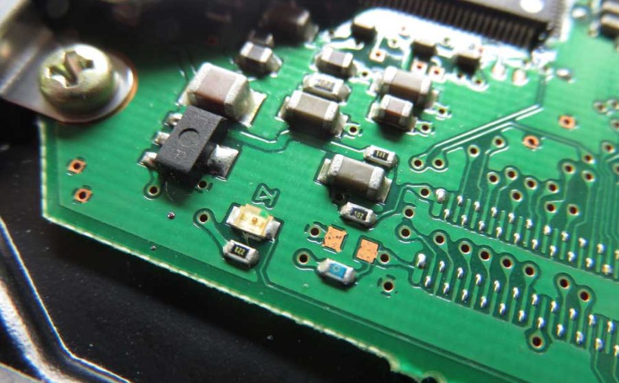
A proximity sensor is a device that provides contact-free detection of moving or stationary objects. It then converts that information into an electrical signal.
A proximity sensor
Source: Wikimedia Commons.
Since the sensor does not need physical contact, it is ideal for working with delicate or unstable objects. Also, it has a long lifespan due to minimal wear, except for the magnetic type.
How Do Proximity Sensors Work?
The operating principles of ultrasonic and infrared proximity sensors are straightforward because they function by transmission and detection/receiving the reflected signal.
A Lego Mindstorms NXT ultrasonic sensor
Source: Wikimedia Commons.
Therefore, we will look at the other three, which operate differently.
Inductive Proximity Sensor Working Principle
This device detects magnetic losses caused by the eddy currents generated by an external magnetic field on the conductive surface. Its detection coil generates an AC electromagnetic field, and whenever a metal object comes close by, the impedance changes due to eddy currents. These changes form the sensor's input.
The sensor and object form a Transformer-like relationship. But there are variations of this working principle, such as all-metal sensors, pulse-response sensors, and aluminum detecting sensors.
Capacitive Proximity Sensor Working Principle
A capacitive sensor checks for capacitance changes between the sensor and sensing object, and this value varies depending on the object size and the distance to it. Usually, the device features two parallel plates, one of them being the sensing surface and the other the object under detection. The changes in capacitance between the two plates form the sensor's input.
Magnetic Proximity Sensor Working Principle
Reed switches control magnetic sensors by turning them on or off.
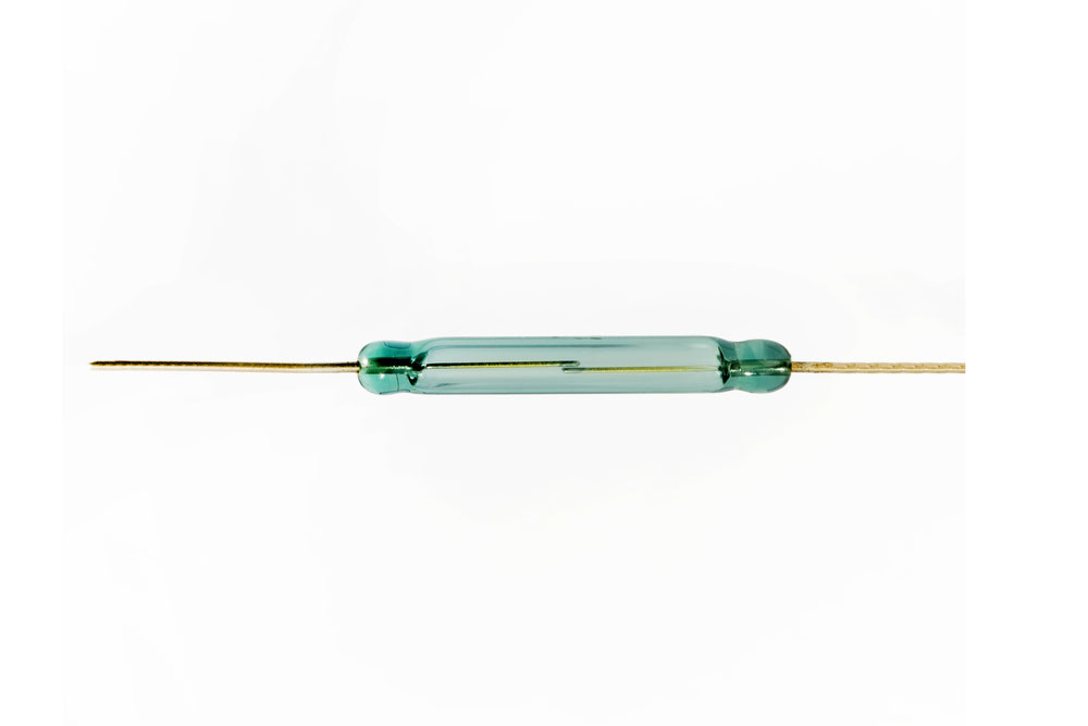
A reed switch
Types Of Proximity Sensors
Proximity sensors are available in five main types, which include the following:
Inductive Proximity Sensors
As the name suggests, these sensors operate using the law of induction, driving a coil and oscillator once the metal object gets to it. It contains four components: a Schmitt trigger, coil, oscillator, and output switching circuit, and the setup only detects metal objects. The device is available in two versions: shielded and unshielded.
Capacitive Proximity Sensors
Unlike inductive sensors, capacitive sensors detect any metallic or non-metallic object because they check for changes in capacitance. Also, they replace the coil with two charging plates, an internal one linked to the oscillator and an external one for sensing.
Ultrasonic Proximity Sensors
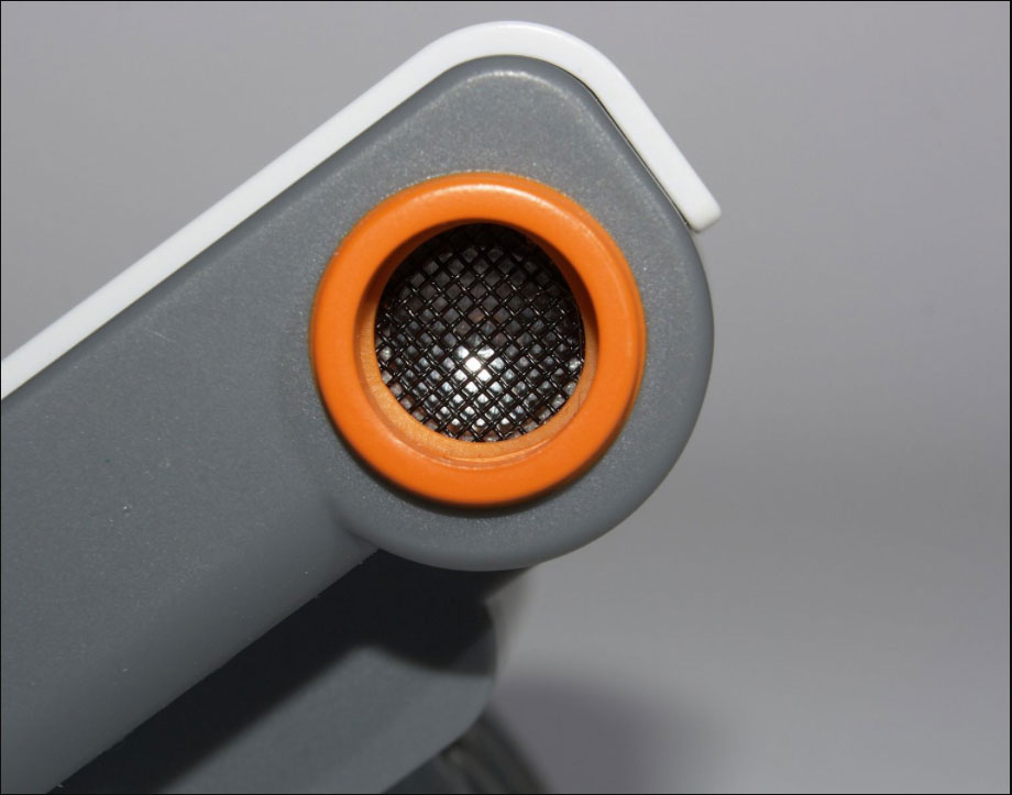
Ultrasonic sensors sense objects by emitting a high-frequency ultrasonic range, then detecting the echo. Therefore, it consists of an ultrasonic transmitter and receiver and can detect objects in liquids, solids, or granular form.
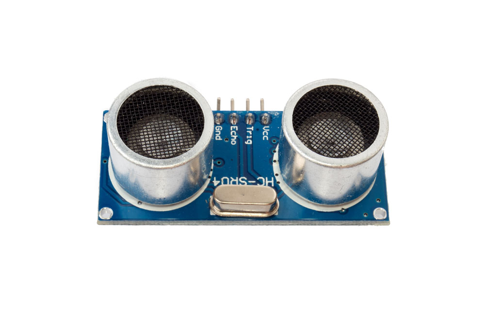
Ultrasonic sensor module
IR Proximity Sensor
An infrared sensor operates by emitting infrared then detecting the reflection using a light sensor/detector. Also, it features a built-in signal processing unit to determine the optical spot on the Position-Sensitive Device (PSD).
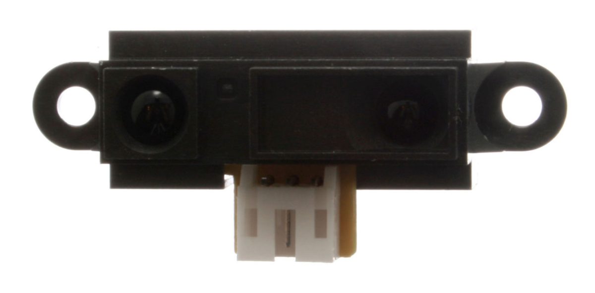
An infrared proximity sensor
Source: Wikimedia Commons.
Magnetic Proximity Sensors
As the name suggests, magnetic proximity sensors detect magnetic objects. Usually, they contain reed switches but can operate using variable reluctance, magneto-resistive, inductive, or hall effect principles.
Special Offer: Get $100 off your order!
Please email [email protected] for details.
Proximity Sensor Features
- Contactless sensing
- Suitability for a wide range of applications
- Long service life
- High-speed response rate
- Not affected by surface conditions (colors of objects, ambient temperature, etc.)
- Usable across a wide temperature range
- Two-wire sensors
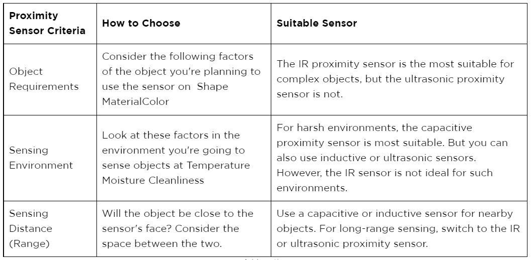
How To Choose A Suitable Proximity Sensor?
When looking for a proximity sensor, you need to consider the intended purpose as broken down in the following criteria:
Proximity Sensor Circuits: How To Make A Proximity Sensor
Even though there are five types of proximity sensors, we will look at the IR circuit because it is smaller, more affordable, and can measure distances to soft objects. You will require the following components:
- Infrared LED
- Infrared photodiode
- Red LED
- IC LM358 op-amp
- Preset (potentiometer)
- Two 220 ohm resistors
- One 10k ohm resistor
- Power supply (5-6V)
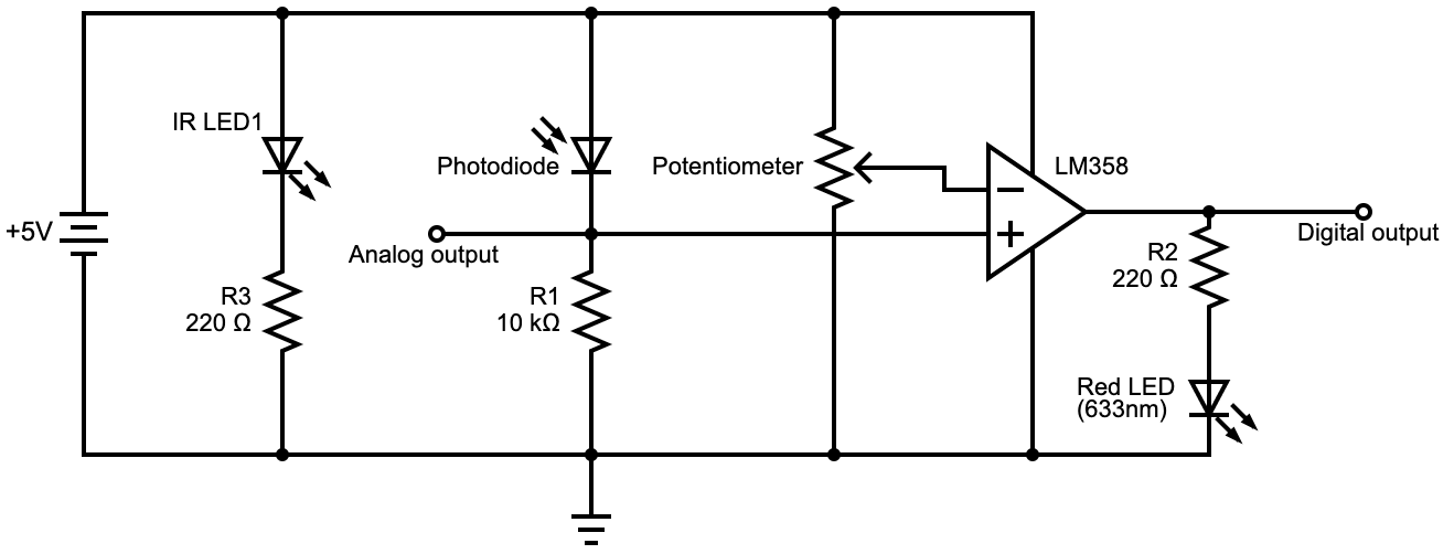
An infrared proximity sensor circuit diagram
The circuit has two LEDs parallel to each other. One is the IR emitting LED, which functions as the transmitter, and the other is the photodiode (receiver). If it encounters an obstacle ahead, the emitted IR rays get reflected, and the photodiode intercepts them.
Once intercepted, the resistance in the photodiode decreases, creating an electrical signal. This signal is the voltage going through R1 and feeds into the non-inverting end of the op-amp.
The purpose of the op-amp is to compare the input from the non-inverting pin and the potentiometer's threshold voltage input coming in from the inverting pin. If the input voltage from the inverting pin is higher than that from the non-inverting pin, the op-amp output will be LOW. Otherwise, it will be HIGH, and this is when the sensor detects an object.
Op-Amp Output
The other function of the op-amp is to convert the circuit's analog signal into a digital one. The digital output signal is either high or low, and you can use this as the input to a robot's motor to help navigate it along clear paths.
But you can also get analog output from the circuit, although this won't be useful unless it goes through an external microcontroller. This connection eliminates the need for the op-amp, but the microcontroller does the same function (analog to digital signal conversion).
What About Ambient Light and Sunlight?
The circuit above has one major flaw. Sunlight and ambient light affect its reliability, so it only detects accurately in dark environments. The solution is to build a circuit that emits and detects a specific infrared frequency to avoid the other light frequencies.

An infrared proximity sensor circuit diagram is immune to sunlight and ambient light.
As you can see, the circuit has two main sections, each with a different integrated circuit. The LM567 is the primary part, and its purpose is to transmit and receive infrared light.
However, the circuit has a more specific IR emission because R3 and C2 determine the internal oscillator frequency. This frequency sets the chip's center frequency, generating a constant high at pin8. They then feed this frequency to the IR diode D1 (LD274) via a current-controlled stage consisting of T1 and R2.
Meanwhile, pin3 (input) listens for frequencies that equal the chip's center frequency from the BP104 IR receiver (D2).
When the system approaches an object, the IR beam transmitted from D1 gets reflected, and D2 picks up the frequency, directing it to pin3. Since this frequency matches the set center frequency in the IC, the chip recognizes it and switches its output at pin8 from high to low.
Configured as a monostable, the second chip (LM555) receives the low trigger via pin2, then switches its output to high and sounds the buzzer.
This condition persists as long as the IR frequency beams get reflected. However, the LM555 chip can exhibit delays when switching the buzzer off after getting clear of the obstacle. You can adjust this delay using C5 and R9.
You can build other variations using a solitary 567 tone decoder or two LM555 integrated circuits, but the circuit has a similar operation.
Proximity Sensor Arduino Project
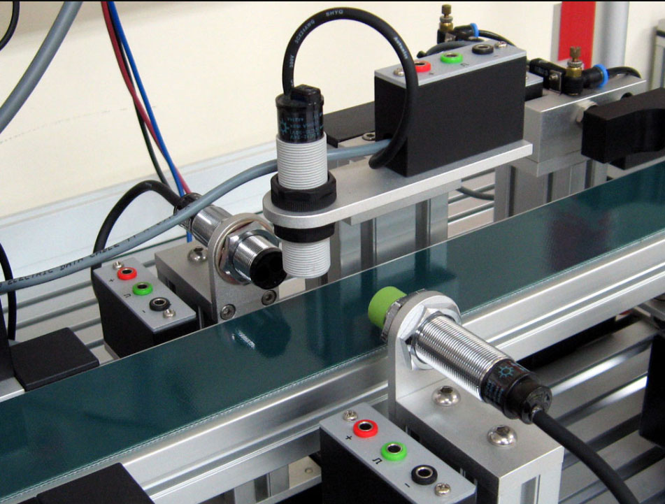
Since we looked at the infrared sensor above, we will try something different this time. Instead of building the custom board from scratch, you can use a ready-built sensor then integrate it with Arduino for your project. Here's how to develop an inductive proximity sensor switch detector.
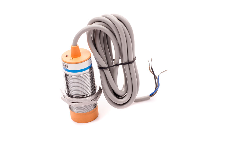
Inductive proximity sensor
Interfacing Inductive Proximity Sensor with Arduino:
You need the following components:
- Arduino Uno R3
- Arduino IDE
- Inductive proximity sensor DC 3-wire model (LJ12A3-4-Z/BY)
- 9V battery
- Battery clips with bare leads
- 400 tie-point breadboard
- Male-to-male jumper wire
- Two 10k resistors
Circuit
Connect the resistors in the breadboard. Their purpose is to reduce the input voltage for the Arduino Uno R3 from 9V to 4.5V.
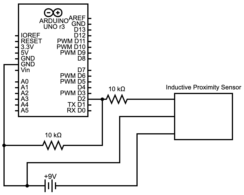
How to interface an inductive proximity sensor with Arduino
Inductive Proximity Sensor Arduino Code
After setting up the inductive sensor, open the Arduino IDE and upload the following code:

Arduino code for displaying whether the sensor detects an object or not on the screen
Arduino reads the sensor's output every 0.5 seconds, which should be low when there is no object close by and high if there is an obstacle. But remember that this sensor only detects metal objects, and the output will either be "no Object" or "Object Detected" every half a second.
Depending on what suits your project, you can replace the sensor with any of the four other sensor types.
Proximity Sensor Applications
Applications for proximity sensors include the following:
- Standard object position detection
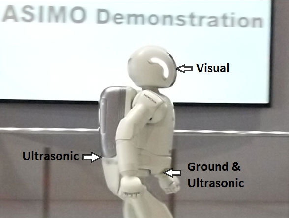
A robot with two ultrasonic sensors
Source: Wikimedia Commons.
- Transportation, logistics, and supply chain
- Level detection
- Process control
- Agriculture
- Quality assurance and inspection
- Food processing
Summary
To sum up, proximity sensors are critical devices in our evolving technological world because they come in handy in several applications. Key among them is in the automotive industry, where they provide driver assistance data. They are also crucial in the development of autonomous vehicles.
If you need the device for your project, contact us with your design, and we will assemble the PCB at a reasonable price.
Special Offer: Get $100 off your order!
Please email [email protected] for details.