Modern cells use lithium-based intercalation compounds for the positive electrode. It is more stable than highly reactive pure lithium.
Furthermore, some of these materials react with the electrode after ion transfer. They become part of the material and lose their charge due to electrochemical reactions.
The free ions' supply gradually depletes, resulting in reduced battery life, and each current charging time causes the electrodes to expand in volume. This damages the structure, minimizing the electrodes' ability to accommodate free ions.
See below how a researchable primary battery pack works and how you can design a Li-Po battery charging circuit.
Contents
- Li-Po Battery Charger design Circuit--Li-Po Battery Charger Introduction
- Li-Po Battery Charger design Circuit
- Li-Po Battery Charger design Circuit--the Working principle
- Discharge/Charge
- Energy Density vs. Power Density
- How to Design Lipo Battery Charger Circuit
- Li-Po Battery Charger design Circuit--PCB layout
- Circuit operation
- In Summary
Special Offer: Get $100 off your order!
Please email [email protected] for details.
Li-Po Battery Charger design Circuit--Li-Po Battery Charger Introduction
(Lithium-ion battery monitoring electronics)
Source: Wikipedia
Firstly, batteries with a recharge cycle are made with lithium-polymer. It uses Lithium-ion technology enclosed in a flexible pouch. Its soft, adjustable bag makes it very light while sacrificing some mechanical strength.
The individual batteries used originally were lithium metal batteries, and we now use Lithium Polymer Batteries.
Li-Po batteries use polymer electrolytes. This, instead of lithium salt electrolytes bound in organic solvents such as Ethylene carbonate. Based on its technology, a Li-Po battery produces a different voltage limit.
Cells based on lithium metal oxide discharge to two Five-three.0 V (charged). Whereas cells in series configuration based on lithium iron phosphate discharge to one. Eight -two.0 V (set). In addition, the charging constant current limit typically equals one-fifth of the battery rating in mAH.
Li-Po batteries can also suffer from an increased charging method process. It can also suffer from deep discharges, over-heating, and short circuits.
Any of these problems could result in permanent damage to the battery or even an explosion. Designers take great care with Li-Po battery charger circuit diagrams to avoid such issues.
Special Offer: Get $100 off your order!
Please email [email protected] for details.
Li-Po Battery Charger design Circuit
(Positive and negative electrode vs. anode and cathode for a secondary battery)
Source: Wikipedia
Li-Po Battery Charger design Circuit--the Working principle
The internal components are an anode, cathode, separator, electrolyte, and two electrodes (positive and negative).
You store lithium in the anode and cathode. As the lithium ions pass through the division from the cathode to the anode, the electrolyte carries them. Free electrons are produced at the anode during lithium-ion movement, creating a charge level at the positive current collector.
A powered device (cell phone, computer, etc.) connects to a constant battery current collector, leading to a negative collector. Lastly, a separator prevents electrons from flowing through the battery.
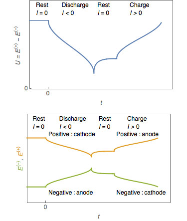
Discharge/Charge
The anode releases lithium ions to the cathode during discharge, which generates a flow of electrons from left to right and vice versa. The cathode releases lithium ions when you connect the device. Finally, the anode receives them when the cathode connects.
Energy Density vs. Power Density
Power density and energy density are two of the most common concepts associated with batteries. You measure a battery's energy density and a battery life span in watt-hours per kilogram (Wh/kg). This represents the amount of energy it can store concerning its mass.
Furthermore, you measure the power density in watts per kilogram (W/kg) and relate it to its mass in its ability to generate power.
Imagine draining a pool to gain a better understanding. Power density is comparable to draining the pool as quickly as possible, while energy density is similar to the size of the pool.
How to Design Lipo Battery Charger Circuit
Li-Po Battery Charger design Circuit--PCB layout
Today, many solutions work with Li-Po batteries. Firstly, observe the circuit diagram for the TP4056 module. It is common to see tiny chips like the TP4056/YP4056 on display. Follow the steps below to fabricate the chip:
- Using a soldering pencil, locate the resistor position on the top of the PCB and carefully remove it.
- From the solder pads, extend short lengths of two multi-strand wires.
- Attach the new resistor network (1K2 1'4 "W resistor and the preset potentiometer) to the wire ends, i.e., replace the original R4 SMD resistor.
- Connect a 3.7 V Li-Po battery center pole to the module output, feed power to the module's input, and observe the onboard LEDs to ensure you're doing everything right.
Circuit operation
(Symbol of a battery power source)
On a 3.7 V, li-polymer battery, you set pin3 of the opamp. This is so that the opamp's output goes high as soon as the battery reaches 4.2 V.
You will set the input constant voltage regulator output for a single cell. This is to compensate for the forward voltage drop accompanied by the diode. Then, you need to adjust this value to 4.2 x 3 + 0.6 = 13.2 V for three cells in a series configuration.
The battery connects across the shown position, ensuring that its constant charging rate can pull power from the voltage regulator. If it were not connected, the battery would be in a discharged state, so it would remove the voltage regulator of the supply level to the battery's current constant voltage, let's say 3.6 V.
Since the pin3 of the operational amplifier is below the reference voltage level, the output of pin2, PIN6, or IC1 fixed to IC2 is very low.
In the process of accumulating its charge limit, the battery voltage level climbs until it reaches 4.2 V, which pulls pin3 of the AMP rating just above pin2 so that its output goes instantly high.
By pressing the above button, the indicator LED will turn on, switching on the Q1 2N222 transistor connected across the D2 pin of the LM 324.
After this happens, the pin of the LM 324 grounds itself, causing it to cut off its output supply to the lipo battery.
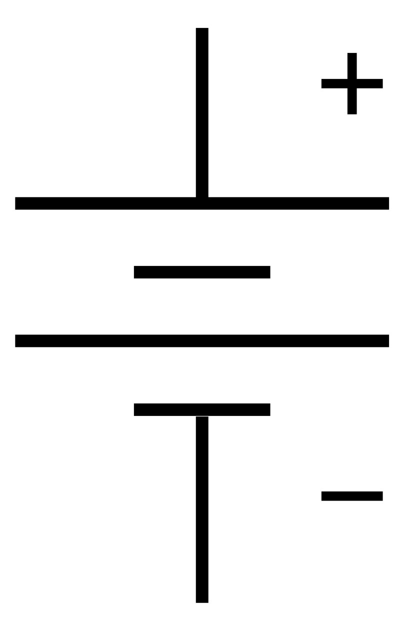
(Battery positive and negative)
In Summary
In conclusion, you will use different LiPo batteries in applications where weight is a significant concern. Typical applications are radio-controlled model flights, RC toys, handheld critical devices, and more. However, they are not without their shortcomings. After completing a charge cycle once, they lose their ability to hold a charge.
As a result, your batteries will no longer be as strong after a few charges. They will provide you with less power. Generally, batteries have recharge cycles of about two years.
Lastly, if you have any questions about Li-Po batteries, please feel free to contact us. Our team will be happy to assist you.
Special Offer: Get $100 off your order!
Please email [email protected] for details.