Why do you need a Flex Sensor circuit? Well, let's look at two scenarios.
First, you want to confirm if your door is open or not. All you need to do is place a sensor at the door edge. That way, your device will flex. As a result, the sensor's parameters will change—which you could design to offer an alert.
Second, you want to know the flex angle of your device. You can place the sensor on your instrument, giving you the result in electrical parameters.
It sounds easy to use, right? True, but there are still a few things to understand before handling the sensor like a pro.
Interestingly, we created this article to help you understand the topic by highlighting the types, how the flex sensor works, and more.
Keep reading!
Contents
- What is a Flex Sensor?
- Construction of the Flex Sensor
- How Do You Use the Flex Sensor?
- The Types of Flex Sensors
- Fiber Optic Flex Sensor
- Velostat Flex Sensor
- Conductive Ink-Based Flex Sensor
- Capacitive Flex Sensor
- How Does the Flex Sensor Work?
- Basic Flex Sensor Circuit
- How to You Wire the Flex Sensor to the Arduino UNO
- How Do You Interface the Flex Sensor with Arduino?
- Steps
- Controlling a Servo Using the Arduino and Flex Sensor
- Flex Sensor Applications
- Final Words
Special Offer: Get $100 off your order!
Please email [email protected] for details.
What is a Flex Sensor?
The flex sensor is a cost-effective and straightforward device that helps you to measure the amount of bending.
Further, you can call the device a Flexible Potentiometer because its resistance is directly proportional to the amount of deflection.
Also, the two-terminal device changes its terminal resistance when you bend the sensor. Plus, it doesn't have polarized terminals. Hence, there's no negative or positive. That is, you can connect the P1 to the positive power source while you connect the P2 to the ground.
Here's a summary of the specification and characteristics of the flex sensor:
| Parameters | Specifications |
| Flat resistance | 25K Ohms |
| Operating temperature | -450C to 800C |
| Bend resistance range | 45K to 125K Ohms |
| How it operates | On low Voltage |
| Power rating | Continuous (0.5W), Peak (1W) |
| Resistance tolerance | +/- 30% |
| Operating voltage | 0-5V |
The flex sensors come in two sizes: 2.2" and 4.5." And each of the sensors is 5.588cm and 11.43cm, respectively.
Construction of the Flex Sensor
The device has a deposition of conductive ink on a phenolic resin substrate. Also, the top of the device has a segmented conductor—that helps generate a flexible potentiometer. With this, the resistance changes with deflection.
How Do You Use the Flex Sensor?
The best way to use the flex sensor is by bending it in one direction. That is, the direction you tilt the device should be away from the ink. While at it, avoid turning your sensor close to the base because it's fragile.
The Types of Flex Sensors
With a good idea of what the flex sensor is, let's dive into the types:
Fiber Optic Flex Sensor
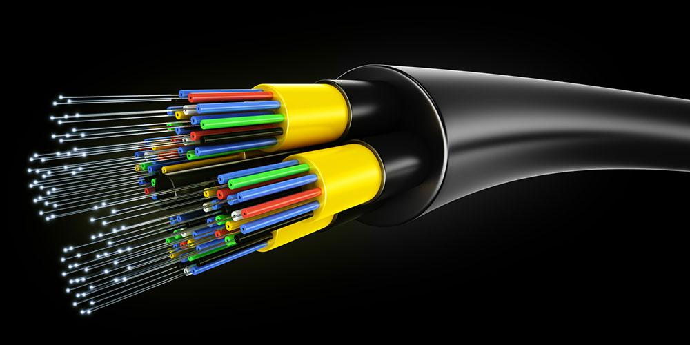
Fiber Optic Flex Sensor
As the name suggests, it's a fiber-based device that uses optical fibers. So, it helps to determine specific quantities like acceleration, displacement, pressure, mechanical strain, etc.
The device's working principle relies on transmitting light from any superluminescent source through an optical fiber.
Consequently, the device's parameters will change (either the fiber Bragg gratings or optical fiber). Then, it will get to a detector that measures the changes.
Velostat Flex Sensor
This device is a piezoresistive plastic film. And when there's a decrease in resistance, the Velostat reacts to pressure.
This sensor is between two layers of neoprene, so it doesn't necessarily react to bend. Instead, it exerts pressure as you turn the device. In other words, the device allows you to measure angles through pressure.
Conductive Ink-Based Flex Sensor
The unipolar sensor usually changes when you bend the device in one direction. This flex sensor is the most common type (the one we focused on in this article). And it's because it has multiple applications.
But if you bend it in the opposite direction, it doesn't change resistance, and it's at risk of damage.
Capacitive Flex Sensor
This type of flex sensor has two layers of capacitor plates. The first surface combines a capacitor plate on a flexible insulating substrate. The next layer has a second capacitor plate on the flexible substrate.
Also, you can adapt this device's flexible substrate to be a squeezable and elastic dielectric between both capacitor plates. So, you can create a glove that will integrate into a body part with flexure points like the fingers or hands due to the sensor's nature.
How Does the Flex Sensor Work?
As we mentioned, flex sensors work when you bend the strip. So, if you twist the strip, the resistance will change. And you can use a controller to measure the change in resistance.
Also, the change in resistance relies on surface linearity. For instance, if you twist the sensor to 900, the opposition will differ. And the same thing happens when you turn the device to 450.
In other words, your resistance rises when your angle increases. So, if you measure the opposition, it's easy to know the deflection of the sensor.
Special Offer: Get $100 off your order!
Please email [email protected] for details.
Basic Flex Sensor Circuit
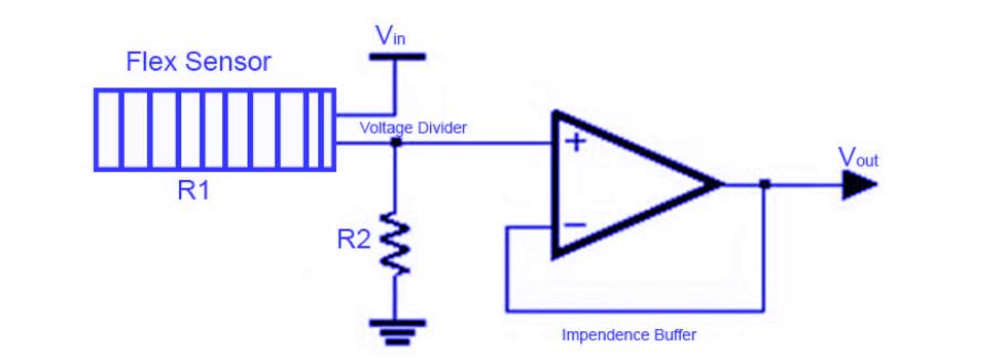
Basic Flex Sensor Circuit
Before you read a flex sensor, creating a voltage divider is crucial because it's a variable resistor. And you can do this by connecting your device with a 47k Ohms resistor (fixed value). But first, start by linking one end of your sensor to power. Then, attach the other end of the sensor to a pull-down resistor.
Afterward, attach the point between the pull-down resistor and flex sensor to the Arduino (the ADC input). With this, Arduino's ADC input can read the variable voltage output.
Also, it's important to note that your output voltage should be the voltage across the pull-down resistor. And you can represent the configuration in the equation below:
Vo = Vcc R/ R + Rolex
The equation shows that an increase in the bend radius causes an output voltage increase. So, if you have a 47K pull-down resistor with a 6V supply when the sensor is standard at 00, your resistance will be pretty low (about 26KΩ).
Hence your equation will be:
Vo = 6V 47KΩ/ 47KΩ+ 26KΩ
= 3.86V
How to You Wire the Flex Sensor to the Arduino UNO
One of the best ways to connect a flex sensor to the Arduino is by making a series connection. The series connection should involve the flex sensor and 47KΩ pull-down resistor. That way, you'll create a voltage divider.
With this, get the point between the FSR and pull-down resistor. Then, connect that point to the Arduino's A0 ADC input.
How Do You Interface the Flex Sensor with Arduino?
The materials you'll need for interfacing the flex sensor with Arduino include:
- LED
- Breadboard
- Resistors (10 and 220 Ohms)
- Flex Sensor
- Arduino UNO
Steps
Step 1- Make Reference to the Circuit Diagram
When you look closely at the breadboard schematic's circuit diagram, the connections should be pretty straightforward.
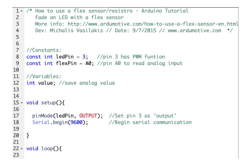
Step 2- Use the Code
Typically, the flex sensor comes with a range of about 10K to 35K. So, your device won't give you a total analog value (0 - 1023) or volt range (0 – 5). Hence, the best approach is to find the analog value of bending your device. And you can use a serial monitor to get the analog value. Your results should range from 700 to 900.
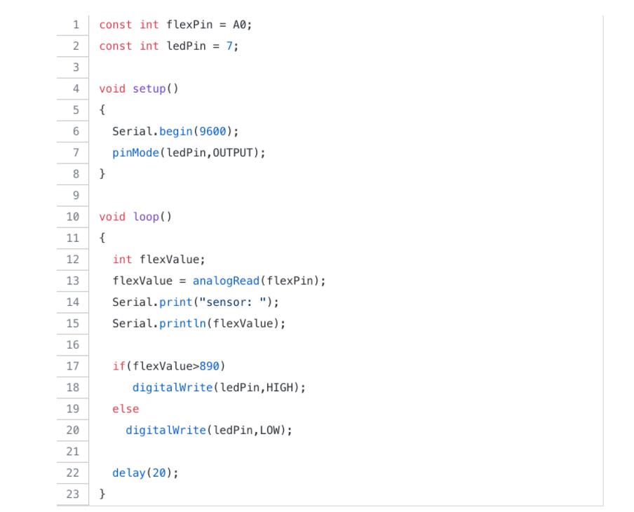
How does it work?
- Get readings from your flex sensor by reading the analog values
-> Value = analogRead (flexing);
- Map your two values: analog values (700 – 900), pwm values (0 - 255)
-> Value = map(value, 700, 900, 0, 255);
- Direct your pwm value to led
-> analogWrite (ledPin, value);
With this, you can proceed to download the plugin (codebender). Then, click on the "Run on Arduino Button,"—which helps program your Arduino. But this applies if you have a programmed Arduino board.
Afterward, start the serial communication on your Arduino board by pressing the connect button. While you're at it, feel free to tweak the codes. For instance, you can change the map function values. All you need to do is tap the "Edit" button.
Controlling a Servo Using the Arduino and Flex Sensor
Controlling a Servo with the Arduino and flex sensor is like an extension of the first procedure. And it's because to nail this process; you need data from interfacing the sensor with the Arduino.
The circuit diagram of this process is similar to the previous one. The only difference is that you'll attach the servo motor to the Arduino UNO's Digital I/O pin 11.
And you can use the code below to regulate a servo motor. But, it's important to note that the code depends on your flex sensor's bend—because the servo motor's angle will change.

Flex Sensor Applications
Flex sensors have a wide application. And they work effectively in areas that require the measurement of a device's angle or accurate motion. So, it's no surprise that you can use it in different sizes and shapes.
Some applications include:
- Fitness devices
- Industrial Controls
- Angular Displacement Measurement
- Computer peripherals
- Musical Instruments
- Robotics
- Automotive
- Motion Control
- Medical Instruments
- Physical Therapy
- VR Equipment
Final Words
From the look of things, the Flex Sensor Circuit is an ideal option if you want to deal with applications that require accurate motion measurement or angle. And it comes in different types. So, studying each variety is crucial, and choosing what best suits your project.
What do you think about the flex sensor circuit? Do you need help with the device for your project? You can reach us, and we’ll be glad to help.
Special Offer: Get $100 off your order!
Please email [email protected] for details.