
LED bulb circuit is the lighting technology that fast replaces incandescent bulbs and fluorescent lamps due to their high efficiency in energy emission. Currently, you can get a LED lamp with 250 lumens per watt (Lm/W) efficiency. Additionally, the long life of LEDs compared to any incandescent lamps make them 50 times more efficient for lighting.
Notably, LED lamps to use a LED driver circuit to conduct their operation. In this case, however, we tested many LEDs in series and constructed a simple LED bulb circuit with similar effects to an LED driver circuitry. Not only have we found the LED bulbs to have high energy efficiency, but we have also managed to make a lower wattage LED.
We’re going to take you through the whole process stepwise with the guideline below. But first, let us tackle the basics of LED lights.
What is a LED Bulb?
A LED light bulb, sometimes referred to as a LED lamp, is an electronic lighting component that uses light-emitting diodes (hence the name LEDs).
In other terms, we consider it a type of diode that you can use as an optoelectronic device that carries out conduction when forward biased. Further, it emits electric lighting energy in the form of visible bands on the electromagnetic spectrum. In this way, we end up seeing visible light that radiates from high-power LED lights. In terms of application, simple circuits are preferable for some low-power indicator light-emitting diodes.
The downside of over-exposure to LED light, particularly blue light, can increase eye strain and pose health problems such as macular degeneration. Better regulation of time spent on gadgets such as phones and laptops can therefore be of great help.
We can design LED drivers in two ways;
- By using a transformer-based linear regulator, or
- By using a regular transformer or a switched-mode power supply.
Why are we using LED bulbs?
- You can incorporate the LED current in several electronic components that include illuminations and lights.
- What’s more, some LED bulb types have high efficiency when consuming power, are small in size, and provide better illumination. A particular example is White light LEDs, which are gaining popularity for the features mentioned.
- Also, it is easy to build the circuit here if you plan on making one on your own. The finished product will also have a long lifespan and are reliable.

(white LED in use).
As we continue through the article, we will learn how to make a simple high-brightness LED bulb circuit with a diagram illustration. When we use the bulb here, we imply that the fitting secs and unit’s shape are similar to an incandescent bulb. However, the bulb’s body only discrete LEDs when we fit it in rows then install it in a cylindrical housing.

(incandescent light lamps)
The cylindrical housing enables the equal and proper distribution of the bulb illumination at a 360° angle. In this way, the entire premise has an equal light illumination.
How Does a LED Bulb Circuit Work?
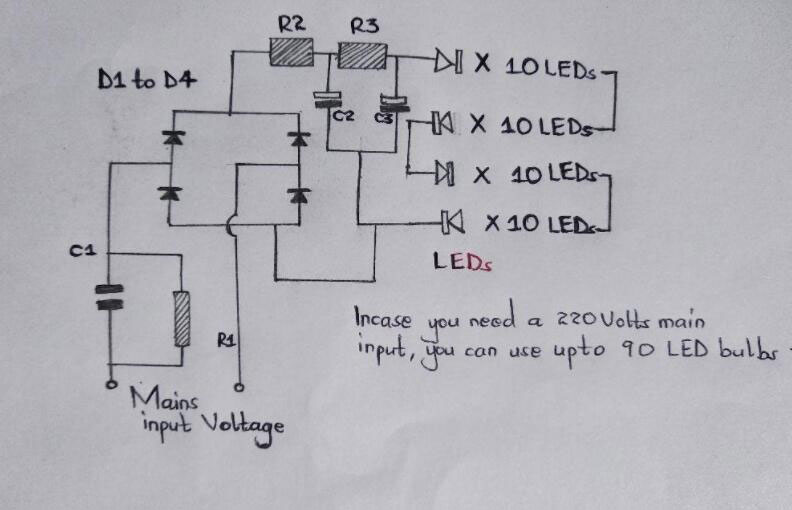
Circuit diagram of a 40 LED bulbs DIY circuit.
The diagram above shows the schemed working of a LED bulb circuit. In further detail, this is how the LED lamp circuit will operate.
(close-up on parts of an LED bulb)
- First, the diagram illustrates a single long series of LEDs that have connections behind each other, thereby forming a long LED chain.
- Specifically, we have used 40 LEDs and connected them in series. Depending on your interest, you can incorporate 45 LED bulbs for a 120V input voltage and about 90 bulbs in series for a current level of about 220V input voltage.
- Further on, you can obtain the figures by dividing the rectified 310 Direct Current (mostly from 220 AC) by the forward voltage that the LED receives.
- Practically, it will be 310/3.3 = giving a total of 93 numbers. Additionally, a 120V input will be – 150/3.3 = 45 numbers. Do note that increasing the number of LEDs above the figures in the examples decreases the risk of switch ON surge. On the contrary, a low LED number will increase the switch ON surge.
- Moreover, a high voltage capacitor is the power supply circuit that powers the LED arrays. You will mostly find its reactance value optimized to step down the high current input to a lower suitable electric current for a LED circuit.
- The capacitor and two resistors positioned at the positive supply suppress the initial electrical power ON surge and other voltage fluctuations. You can achieve the surge correction by introducing the C2 after the bridge, i.e., R3 and R2.
- Finally, the capacitor sinks all the instantaneous voltage surges, therefore, contributing to a safe and clean voltage to the integrated LEDs of the circuit’s preceding stage.
How to Construct the LED Bulb Circuit?
Some cautions you will need to take before beginning the project are;
- First, you will conduct this DIY using a power source directly from the main supply at 230V Alternating Current. Therefore, you have to take care.
- Then, ensure you are familiar with how designing a transformerless power supply works. Failure to know the procedure can be dangerous.
Parts list
The internal LED elements include;
D1—D4 = 1N4007
C2 and C3 = 4.7 µF/250V
C1 = 474/400V or 0.5 µF/400V PPC (polyester capacitor)
R1 = 1M ¼ watt
R2 and R3 = 100 Ohms 1 watt
All LEDs = should be 5mm straw-hat type input = 220/120V mains
X-rated capacitor
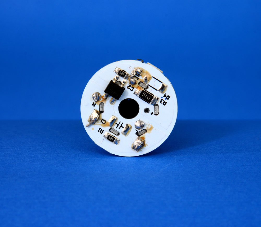
PCB layout design

(a PCB layout design).
Heat sink; A reliable metal heat sink helps in heat dissipation and heat withdrawal, preventing the LEDs in series from overheating.
A dissipator; The dissipator’s main action is to ensure there’s sufficient lighting even under a specific angle.
The driver PCB with LEDs; the LED base often has an aluminum material. The number of LEDs should be equivalent to the bulb design since the correlation helps in heat exchange.
In summary, this is how the components function in the LEDs circuit layout;
- The 0.47µF/400 Volts polyester Capacitor C1 lessens the mains supply voltage.
- The X-Rated Capacitor is a metal film capacitor functioning as a safety capacitor. You will find it placed between the neutral and the line. Should it be overvoltage, a short circuit will arise, followed by a blow in the fuse. In the process, electrical shocks will be limited.
- Then, R1, the bleeder resistor, drains any charge stored from C1, often when you switch off the Alternating Current input.
- Thirdly, when you switch the circuit on, R2 and R3 limit the inrushing current.
- Diodes D1-D4 are the bridge rectifier that rectifies the abridged AC mains voltage to a required voltage.
- Further, capacitor C2 functions as the filter capacitor.
- Last, of all, the D2 Zener diode regulates the circuit, and it can now operate on its own.
Assembly steps
Step 1: Remove the glass bulb carefully.
Step 2: Cautiously open the assembly.
Step 3: Remove any electronics present and discard them.
Step 4: Then, assemble the circuit in a 1-millimeter laminate sheet or a dot matrix PC.
Step 5: Further, with a pair of scissors, cut around the laminating sheet.
Step 6: Proceed to mark the six circular holes’ position on the laminating sheet.
Step 7: Continue by drilling holes (about six) that will suit the LEDs.
Step 8: To keep the assembled LED parts in position, use a bit of adhesive.
Step 9: Now close the assembled circuit once done.
Step 10: Check the internal wiring to ensure they have no contact with each other.
Step 11: Lastly, you can now test the bulb on 230 Volt AC.
How the LED light bulb will work
Often, LEDs require less current to function. In a standard transformer-based regulated power supply, we use series resistors to regulate the current. But, in this DIY, we use the X-rated capacitor to regulate the current in the transformerless power supply circuit.
The capacitor’s reactance limits the available circuit current since the capacitor has a series connection with the AC supply.
The formula for getting the reactance of a capacitor is as follows;
X (c1) = ½ πFC Ohms
F= Frequency of power supply voltage C= Capacitance of the capacitor
FAQs About the Construction of the LED Bulb Circuit
- Can I make a 25 watts LED with a lifetime warranty, lasting over 20 years?
Yes, you can do so even though you must get a Zener diode with a correct selection and rating.
- Which capacitor is suitable for a 90mAh 230V operating current?
C2 and C3 are the known filter capacitors present for most applications.
- I tried out the experiment, but my LED bulbs are not glowing. What could be the issue, and how may I solve it?
An LED bulb may fail to glow for a lot of reasons. It could be that the LED is of poor quality; therefore, they may blow up due to a surge in the electrical current and then stop illuminating. To solve the problem, you can use an NTC or a Zener diode.
Conclusion
In conclusion, we have demonstrated how to design a LED light bulb and how the circuit works. Practically, you may need more resources or a better approach. For experimental purposes, however, this DIY LED is for you.
Remember to handle everything with great care, especially knowing you are dealing with a 230V AC mains supply. For questions and concerns, contact us here. We’ll be glad to help.