

Inverters are critical electrical components in power generation, industrial control, cars, etc., and inverter PCB have made the device tinier for more compact installations.
But making the tiny device have the same reliability credentials as the non-PCB inverter requires careful construction.
So, let’s look at the benefits, types, primary components, and specifications of this device to understand its importance in the industry.
Special Offer: $1 for 5 PCB Assemblies!
Please email [email protected] for details.
What Is an Inverter PCB?
Inverters are electrical devices that convert direct current to alternating current, such as from solar batteries to sockets, for household appliance usage.
An inverter PCB does the same function but fits the DC-to-AC conversion circuitry in a compact board size.
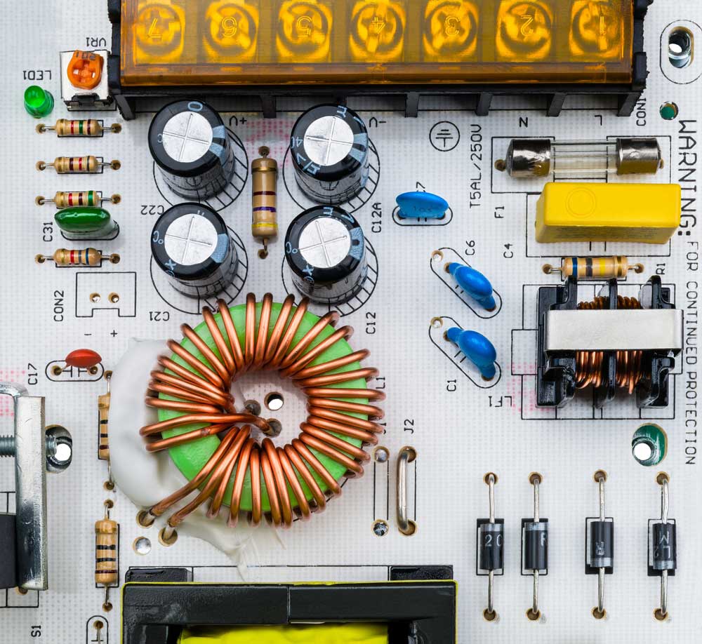
A power supply inverter PCB
Benefits of an Inverter PCB
This inverter circuit board has the following benefits.
-
- Compact Size: Since it uses copper tracks on a board instead of wires, inverter circuit boards are highly compact. And because machines handle the component installation/soldering, you can expect precise calibration, resulting in zero or fewer instances of short-circuiting.
- Easy Diagnosing and Repair: Diagnosing and fixing electrical issues on PCBs is more straightforward than dealing with wires and large circuits.
- Simpler to Assemble: Assembling inverter PCB components is easier than dealing with wires because assembly machines handle most of the work.
- Solid Construction: Circuit boards create tight assemblies with parts attached solidly to the PCB. This design prevents movements that can damage the device.
- Low Noise: Inverter PCBs emit little electrical noise, making them ideal for modern silent devices because they minimize electronic noise pollution.
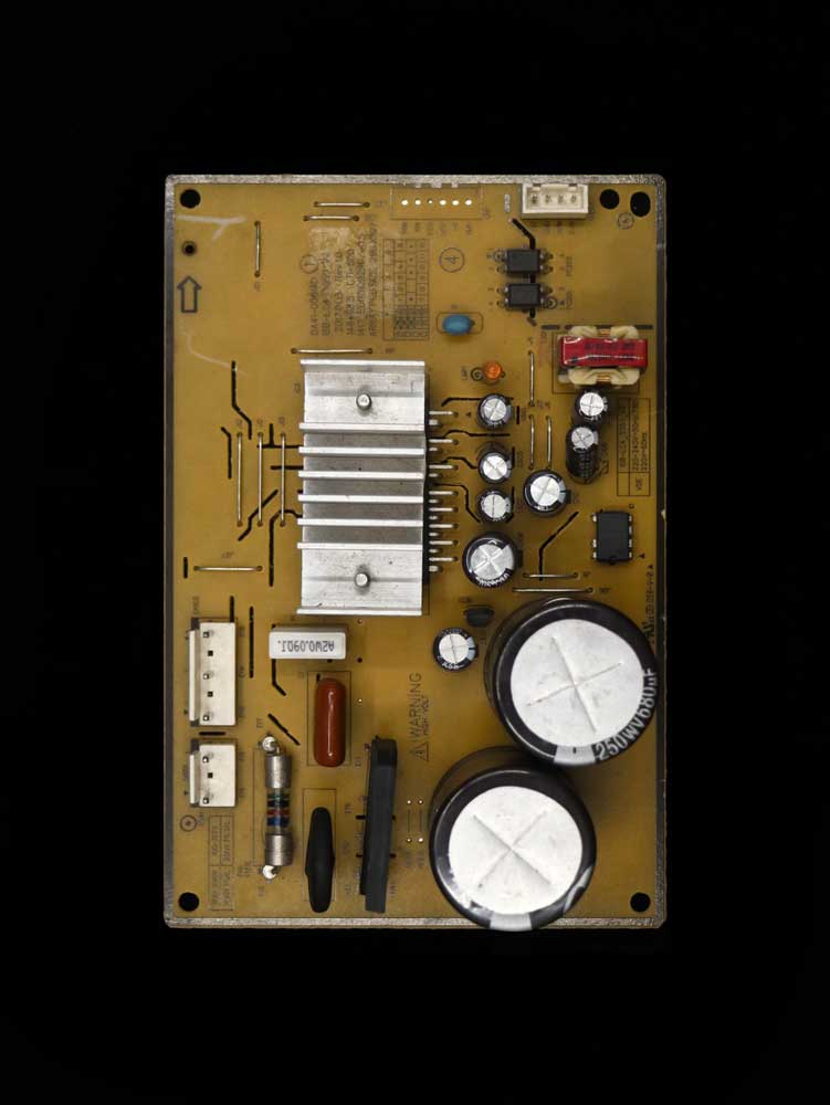
A power-control inverter circuit board
Types of Inverter PCBs
Inverter circuit boards come in these three major types.
Single-Sided Inverter PCB
Single-layer inverter PCBs only have a single base layer with one copper layer. These copper tracks are on one side of the substrate to provide electrical conductivity.
Above this copper foil is a solder mask/resist layer followed by a silkscreen layer to label the sections for easy and precise component assembly.
Single-layer inverter PCBs are the most basic of the three-layered designs but have the lowest manufacturing cost.
Double-Layer Inverter PCB
As the name suggests, a double-layer inverter PCB features two copper conductor layers, one on each side of the base plate substrate layer.
The board can also feature drill holes or through holes for linking components or copper circuits to the other side.
This board is more complex than the single-layer type but not to the level of the multi-layer inverter PCB.
Therefore, it is ideal for middle-level complexity applications, such as power supply units.
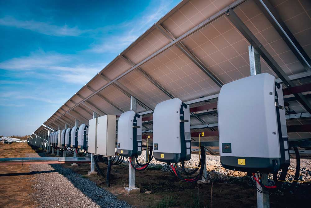
Multiple inverters installed under solar panels for DC to AC conversion
Multilayer Inverter PCB
These DC-to-AC conversion circuit boards are the most expensive and complex units because they feature at least three copper metal layers.
They can have different insulating materials between the conductive layers to prevent short-circuiting and heat damage.
Via holes are also common in these boards for the connection of copper tracks between the layers or to drain heat out from the inner layers.
Special Offer: $1 for 5 PCB Assemblies!
Please email [email protected] for details.
Primary Components of Inverter PCBs
Inverters operate by rapidly switching the direction of a DC input source back and forth, which converts it to an AC output.
It can also have filters and other electronic components to make the output AC sine wave clean enough to inject it into the grid or use it to run household appliances.
Therefore, inverter PCBs contain these primary components.
Microcontroller (Integrated Circuit)
Microcontrollers are the most essential components in the inverter system because they regulate the signal switching.
A single microcontroller can handle different functions, such as controlling the protection systems and generating the PWM signal for direct current switching.
Bipolar Junction Transistor (BJT)
BJTs come in two types, which are NPN and PNP transistors. P and N (positive and negative) refer to the primary charge carriers in the semiconductor.
So, the electronic device has three layers that can regulate the flow of electric current and amplify it.
H-Bridge
An H-bridge is a topology containing four switching devices configured as the branches of the letter H with the load connected as the crossbar.
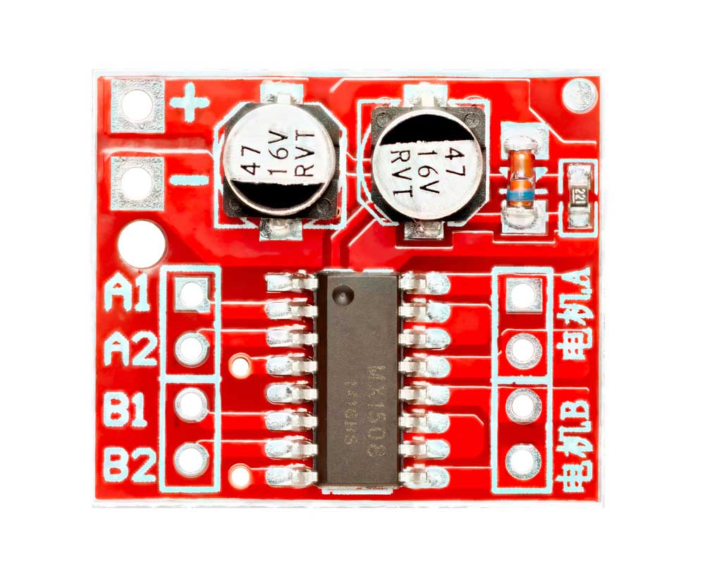
A dual-channel H-bridge motor driver
These switching devices are usually IGBTs (Insulated Gate Bipolar Transistors), MOSFETs, and BJTs integrated to form a single circuit.
The bridge switches the load electric voltage polarity by altering the opening and closing of the four switches.
MOSFET
MOSFETs are voltage-controlled devices that can switch electronic signals at high speeds.
They consist of n-type and p-type semiconductor material channels and are ideal for low-power, high-frequency circuits.
Filters
These devices can allow a single-frequency wave or a narrow band of frequencies from a broad range.
Typical filter types include low band, LC (with an inductor parallel to the capacitor), and RC (with a resistor for power dissipation).
Transformer
Transformers can step up or down alternating current input voltages by varying the number of windings in the primary and secondary coils.
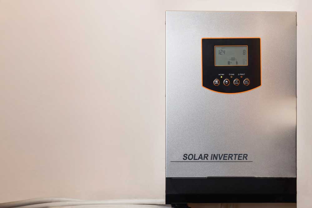
A solar inverter
Specifications To Consider Before Choosing an Inverter PCB
Inverter PCBs undergo stresses from both the internal and external environments. Therefore, you should consider these specifications when choosing one.
Thermal Expansion
The different inverter PCB components described above generate heat when running.
So, the circuit board should be able to tolerate these temperature changes without experiencing damage.
The best way to achieve this temperature tolerance is by building the board using a material having the same thermal expansion rate.
So, be particularly careful when selecting the base substrate and insulation materials, especially in multilayer inverter circuit boards.
Dielectric Loss
This loss refers to the energy wastage due to heating the dielectric material in a varying electric field.
So, the higher the dielectric loss, the higher the signal wastage, resulting in losses when converting DC to AC.
Therefore, you should pick an inverter PCB with zero or minimal losses to cut wastage.
This efficiency is vital for solar installations to maximize the current going into the grid and reduce wastage of the stored battery power in off-grid systems.
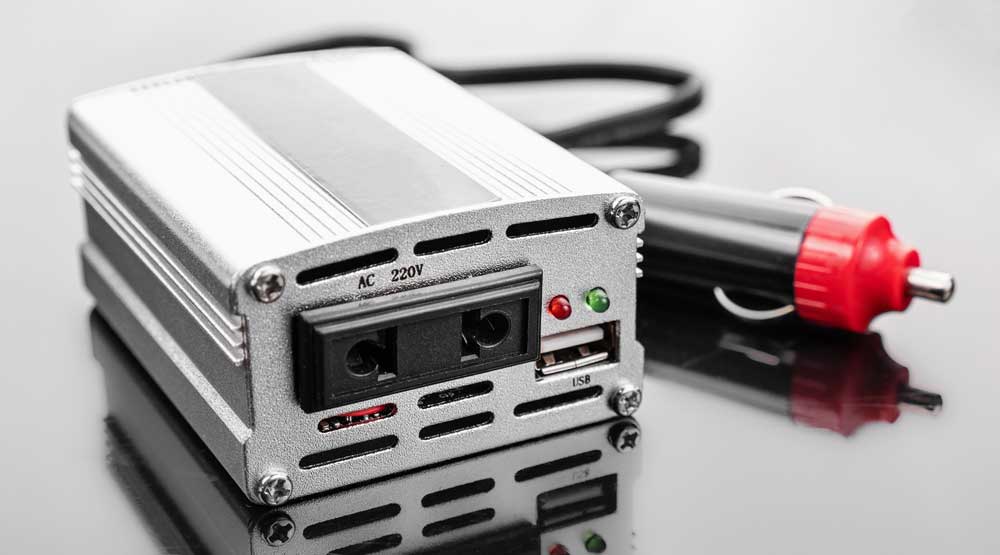
A portable car inverter
Water Absorption
If installing the inverter PCB outdoors or in humid environments, it should withstand these conditions without increasing the dielectric losses or interfering with the relative permittivity (dielectric constant).
Component Resistance
Besides the board specifications, check the quality of the soldered components.
They should match the PCB specifications in impact, heat, and hazardous chemical resistance. Overall, the device should have a high endurance rating.
Applications of Inverter PCBs
These circuit boards are typical in the following areas.
Automotive Industry
Traditional internal combustion vehicles can have 110V or 220V AC output sockets for running household appliances or devices.
These outlets are usually in the trunk and require inverters to convert the battery's DC power to AC.
However, the most common application of inverter PCBs in cars is in electric vehicles. Batteries store charge and release it as direct current.
However, EVs have AC motors to run the wheels because they are more efficient and easier to control than their DC counterparts.
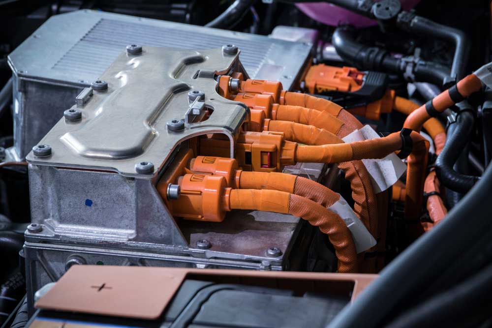
An EV power inverter
Therefore, these vehicles must have efficient inverter PCBs to deliver the required power to the motor(s) from the battery systems.
UPS Systems
Uninterruptible Power Supply Systems are typical in areas requiring smooth, uninterrupted power flow, such as data centers.
These devices power the connected devices directly from the AC mains supply but continuously monitor the incoming current.
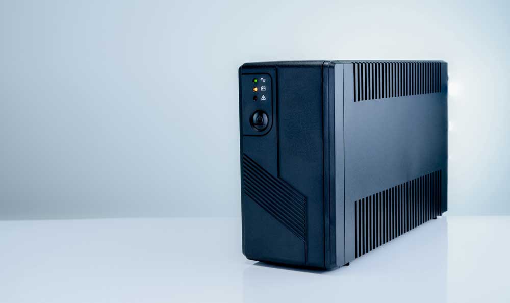
An uninterruptible power supply
If it fluctuates or goes off, the UPS activates its DC-to-AC inverter circuit to power the connected device using the internal/inbuilt battery.
Solar Power Systems
Unlike renewable energy sources like hydro, geothermal, and wind, which can generate alternating current directly, solar panels can only produce direct current.
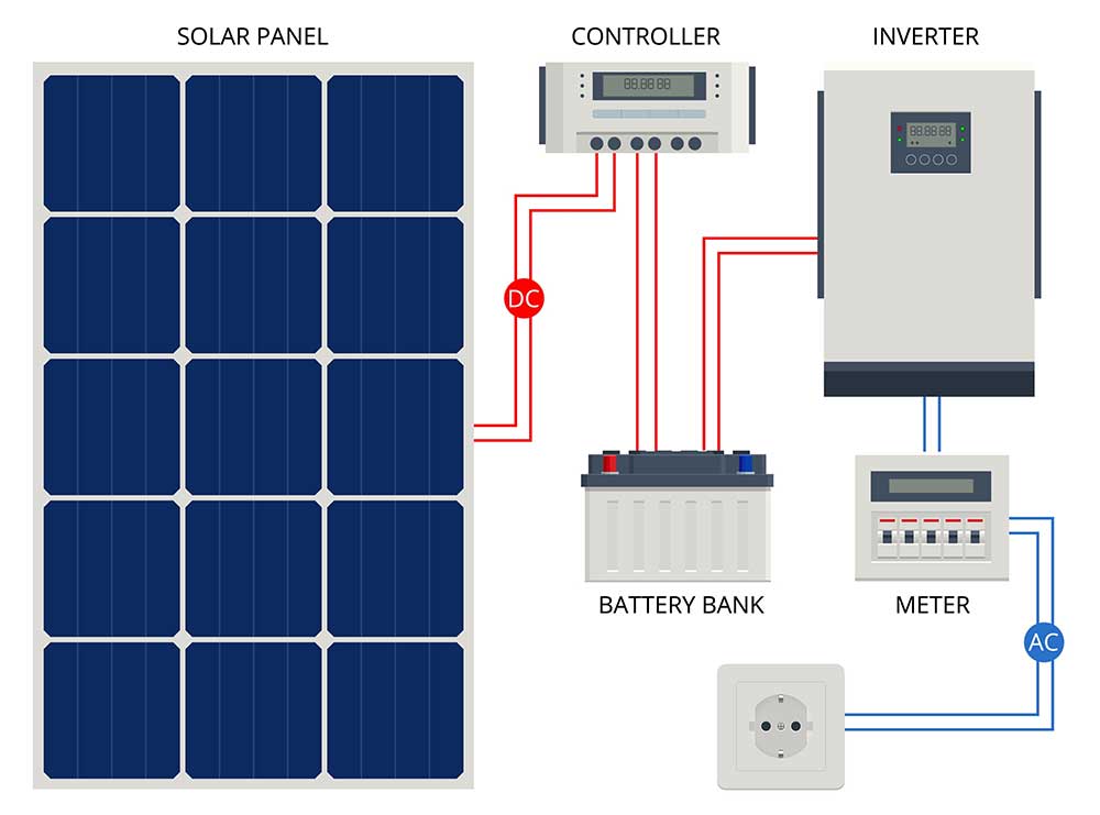
A solar power system with an inverter
Even if you choose to store this power in batteries, you will need a solar power inverter to convert the DC to AC for household use or to sell electricity to the grid.
Industrial Motor Drives
Inverters are critical in automating industrial motor drives because they can regulate the speed and torque of electric motors.
This automation can help to control pumps, conveyors, fans, etc.
Wrap Up
As you can see, inverter circuit boards are invaluable in several industries, particularly EVs and solar installations, because the world is transitioning to green energy and emission-free transportation.
And if you need this PCB for compact and efficient DC-to-AC conversion, we can make one for your project.
Contact us with your design details, and we’ll be in touch with a free quote. That’s it for now. Have a good one!
Special Offer: $1 for 5 PCB Assemblies!
Please email [email protected] for details.