Do you need an appropriate device to aid you measure system frequencies? Get yourself a frequency counter to help you with the measurement.
You can order yourself one from the store, or you can opt to make a simple one for yourself.
And luckily for you, here at OurPCB, we've created a post to guide you through your project.
This article illustrates various configurations of frequency counters, their circuit diagrams, and their applications.
Contents
Frequency Counter Circuit Operating Principle
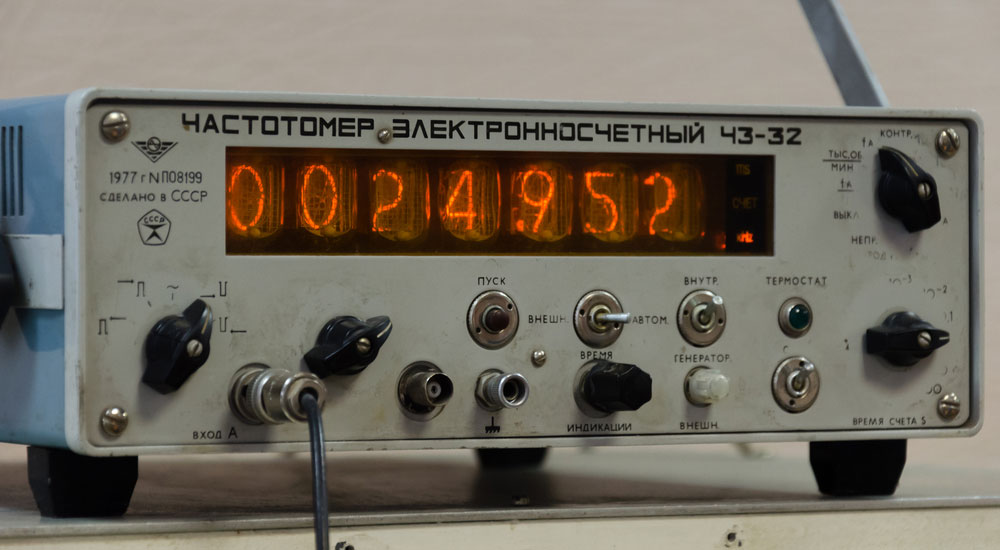
Fig 1: A Laboratory Frequency Counter
A frequency counter or frequency meter counts the number of events within a set period.
Pulses, such as ones from a square wave generator, are fed into the timer/counter.
The counter then causes a time delay, counts, and accumulates the pulses from the input signal at given time intervals. The counter's frequency output in Hertz is then displayed on display.
Therefore, using a frequency counter is an accurate method of measuring frequencies.
Special Offer: Get $100 off your order!
Email [email protected] to get started!
Frequency Counter Circuit Diagram
An 8051 frequency counter circuit diagram consists of an 8051 microcontroller, an LCD, and an IC 555 clock oscillator. Other accessories include a square wave generator, counters, and potential resistors.
The IC 555 timers generate high-accuracy signals after a one-second interval.
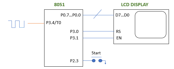
Fig 2: Frequency Counter Circuit Diagram Using Timers
We'll use an Arduino Uno as the wave generator for our case. We'll use the IC 555 timer to produce oscillating signals with the highest time interval of the output waveform.
The square wave generator and the IC 555 timer can be set up as an astable multivibrator.
You can set the discharge and threshold resistors to have a 99% duty cycle to produce the waveform of preference.
The ideal duty cycle formula is,

The 8051 microcontroller has two timers that enable it to work in two modes- mode 0 and mode 1. Here, the mode 0 timer produces a time delay while the square wave generator output pulses are counted by mode 1.
The circuit diagram below shows the configuration of an IC 555 based frequency counter.
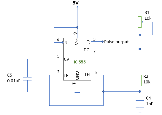
Fig 3: An Ic 555 Frequency Counter Circuit
Two Simple Frequency Counter Circuits
In this section, we will look at two elementary frequency counter circuits.
Frequency Counter Using IC 74LS47
Configuring the IC 555 in AMV mode (Astable Multivibrator Mode) enables it to generate alternate low and high pulses.
In this case, the frequency counter uses exactly 5 volts from a power supply circuit for operation.
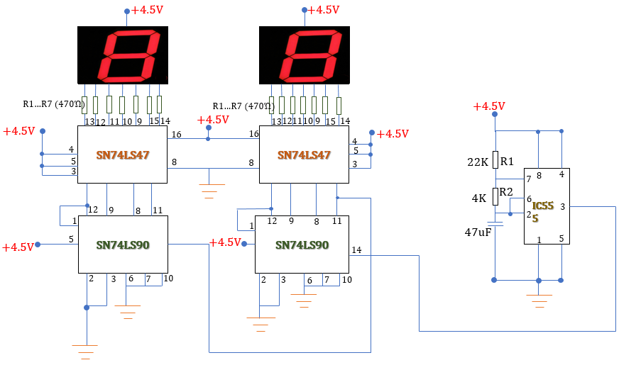
Fig 4: Circuit diagram of a Frequency Counter Using IC 74LS47
Connect 470 Ohms resistors to the display LEDs to maintain constant illumination and safeguard the display LEDs. To count the pulses, we'll connect the IC 74LS47 and the IC 74LS90 counters to the IC 555 pin 3.
The IC 74LS90 uses its input pin 14 to read the signal from the IC 555 timer. It then transforms the call to a binary form that the IC74LS47 can decode. Thus, it outputs it through its output pins 12, 9, 8, and 11.
The decoder IC 74LS47 accepts the binary signal through its input pins 7, 1, 2, and 6. It then decodes the binary data and transmits it to an LCD (on the right) from 1 to 9.
The left display displays a number 0 until a nine is reached on the right-side display.
For the counter to count beyond 9, the tenth pulse will overflow. It happens from pin 11 of the first IC74LS90 to pin 14 of the left or second IC 74LS90.
The above process repeats, with the left display joining to display up until a maximum count of 99. That is, both screens are displaying a 9 and 9.
Therefore, to increase your counter's display, connect another IC 74LS90 and IC 74LS47 pair in the same sequence as above.
Pin 14 of the first IC 74LS90 is an input pin. Therefore, you can connect any pulse you want to count or monitor.
Frequency Counter Circuit Using a Single IC 4033
The IC 4033 frequency counter is more straightforward as it uses one IC 4033 chip and a standard cathode display.
It has an internal binary coded decimal to 7-segment decoder to convert the input clock pulse to a display signal. Furthermore, it uses a single standard cathode display to output 0 to 9 corresponding to the clock signal.
The push-button resets the IC 4033 once you want to start the counting all over again. You use the IC 4033 pin one as an input for the train of pulses from the clock.
To count up and beyond one-digit signals such as two-digit signals, connect your additional circuitry as follows.
- Connect pin 5 of module 1 (the original) to your second module's clock input to count beyond 9.
- You'll then similarly connect another module to measure three-digit clock signals. That's connecting pin 5 of the second module to the third module's clock input.
- Connect all ICs' pin 15 to enable you to use a single reset push button. Also, ensure to connect all power supply lines on a common rail.
- Finally, attach a 0.1 microFarad capacitor to the supply rail for decoupling.
Frequency Counter Circuit Applications

Fig 5: Satellite Dish Antennas
- Measure square wave frequencies.
- To measure the frequency of a signal when a high degree of accuracy is required.
- To measure the signal frequencies at the transmitter and receiver end.
- They're analog to digital converters, frequency dividers, and digital clocks.
- Used in data transmissions as a result of the clock pulses
- To detect frequencies of high power data transfers
Conclusion
Generally, frequency counters are very delicate devices whose accuracy is highly dependent on the accuracy of their timebase. The timebase can change with age, poor design, instability, movement, or even aging.
However, you're working on a frequency project, handle its timebase with care.
Contact us for more information, questions, or clarifications on frequency countersWe'llll get back to you at the soonest time possible.
Special Offer: Get $100 off your order!
Email [email protected] to get started!