

Binary devices like computers and phones run on digital logic circuits, which send signals between chips, components, and networks.
So when designing electronic devices using semiconductors like transistors and integrated circuits, think of the logical level design first.
This design is less detailed than the physical component design, but it will help you create an outline of how you want the devices to communicate. Read on to learn more!
Special Offer: $1 for 5 PCB Assemblies!
Please email [email protected] for details.
Table of Contents
- What Is a Digital Logic Circuit?
- What Is a Digital Logic Gate?
- What About Three-State Logic Gates?
- Combinational vs. Sequential Digital Logic Circuit
- Wrap Up
What Is a Digital Logic Circuit?
A digital logic circuit is an electronic circuit that takes digital binary inputs to perform logical operations, then produces binary outputs.
And each digital logic circuit requires a single input signal or more to give a result.
These binary inputs and outputs (zeros and ones) refer to different voltages.
Usually, zero corresponds to a low voltage level, such as 0V, while one refers to a higher positive voltage, like 3.3V.
But these voltages can vary slightly at the physical level.
So a logic level one can refer to any value above the minimum allowable voltage, while a logic level zero can be any value below the maximum acceptable voltage.
These allowable voltages form the boundary between binary numbers.
And when developing these logic circuits, we use digital logic gates to define the logical operations around the data.
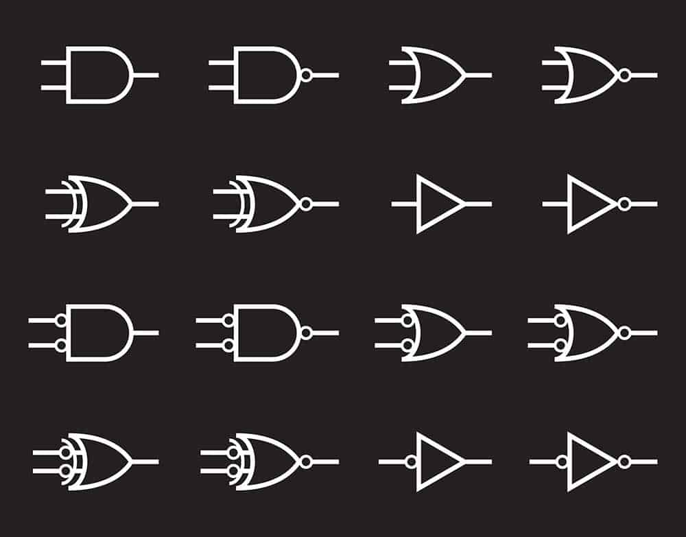
Digital logic gate symbols
Special Offer: $1 for 5 PCB Assemblies!
Please email [email protected] for details.
What Is a Digital Logic Gate?
A digital logic gate is a switching circuit that controls if an input signal will pass to the output side. There are three primary types of logic gates.
Basic Logic Gates
The AND, OR, and NOT gates fall under this category.
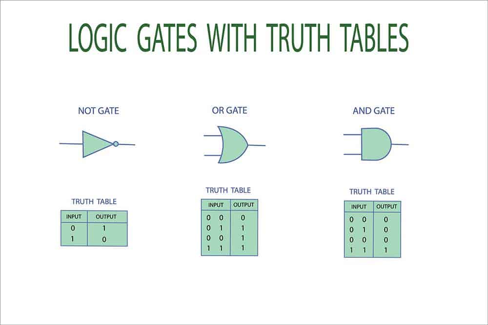
Basic logic gates with their truth tables
AND Gate
This simple logic gate can have two or more inputs but with a single output.
It operates like the “and” operator because the result can only be high (true) if both inputs are true.
Otherwise, the output will be false. True refers to a logic one or high, while false is a logic zero or low (boolean algebra).
The boolean expression for this function is Y(Output)=A.B., and its truth table is as shown below.
| Input (A and B) | Y(Output) | |
| 0 | 0 | 0 |
| 0 | 1 | 0 |
| 1 | 0 | 0 |
| 1 | 1 | 1 |
The primary building blocks of logic gates are transistors, and the base emitter must drive saturation. But the collector voltage can be close to zero.
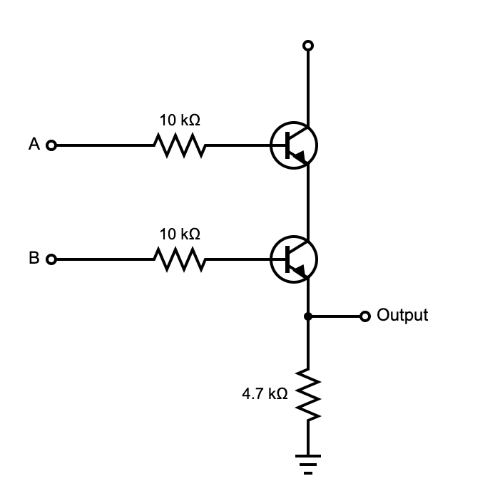
AND digital gate transistors should be in series, and both must be conducting to push a high output.
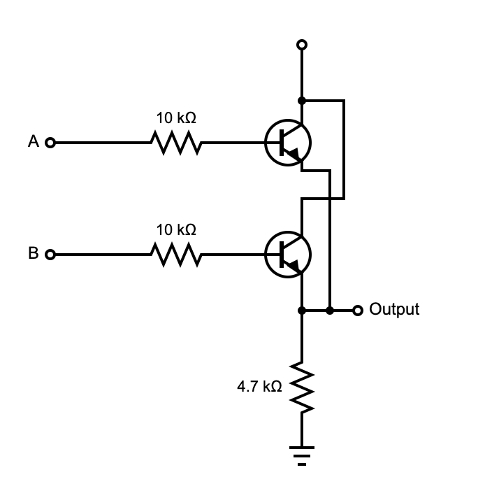
OR Gate
This digital logic gate has the same number of inputs and outputs as the 2-input AND gate. But its result is true if only one of the inputs is true.
So the logical inclusive OR has this mathematical operation Y(Output)=A+B.
| Input (A and B) | Y(Output) | |
| 0 | 0 | 0 |
| 0 | 1 | 1 |
| 1 | 0 | 1 |
| 1 | 1 | 1 |
Here is the OR gate hardware (transistor) implementation diagram.
NOT Gate
NOT gate logic units are unique because they feature a single input and output.
And as the name suggests, the gate inverts the input, giving you an opposite result.
Its boolean operation is Y=A’ Here is its truth table to drive the point home.
| Input (A) | Y(Output) |
| 0 | 1 |
| 1 | 0 |
Universal Logic Gates
These universal gates got their name from their ability to reproduce the functions of basic logic gates.
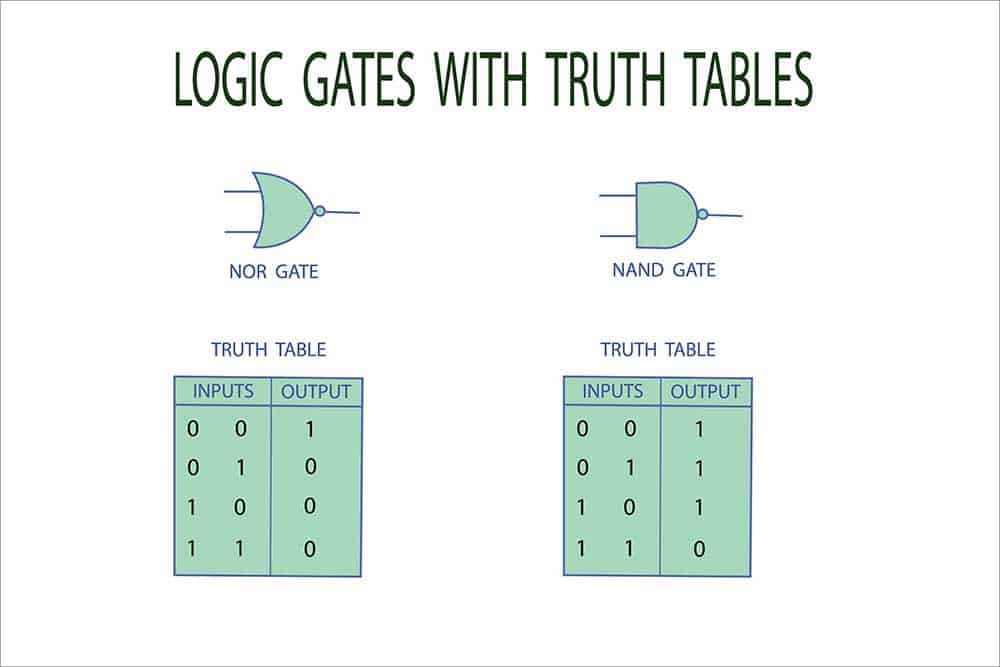
Universal logic gates with their truth tables
NOR Gate
The NOR gate combines an OR gate with an inverter (NOT).
So after outputting the OR gate truth values, it inverts them, resulting in this boolean expression Y(Output)=(A+B)’.
| Input (A and B) | Y(Output) | |
| 0 | 0 | 1 |
| 0 | 1 | 0 |
| 1 | 0 | 0 |
| 1 | 1 | 0 |
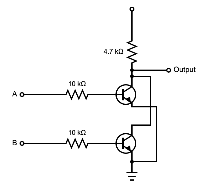
Here is the hardware implementation of NOR gates.
NAND Gate
NAND gates are combinations of AND and NOT gates. They perform the AND operation first, then invert the results using this boolean function Y(Output)=(A.B)’.
| Input (A and B) | Y(Output) | |
| 0 | 0 | 1 |
| 0 | 1 | 1 |
| 1 | 0 | 1 |
| 1 | 1 | 0 |
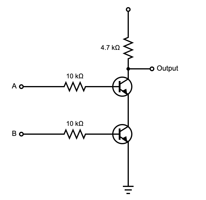
Here is the transistor implementation of this logic gate.
Exclusive Logic Gates
These come in two types.
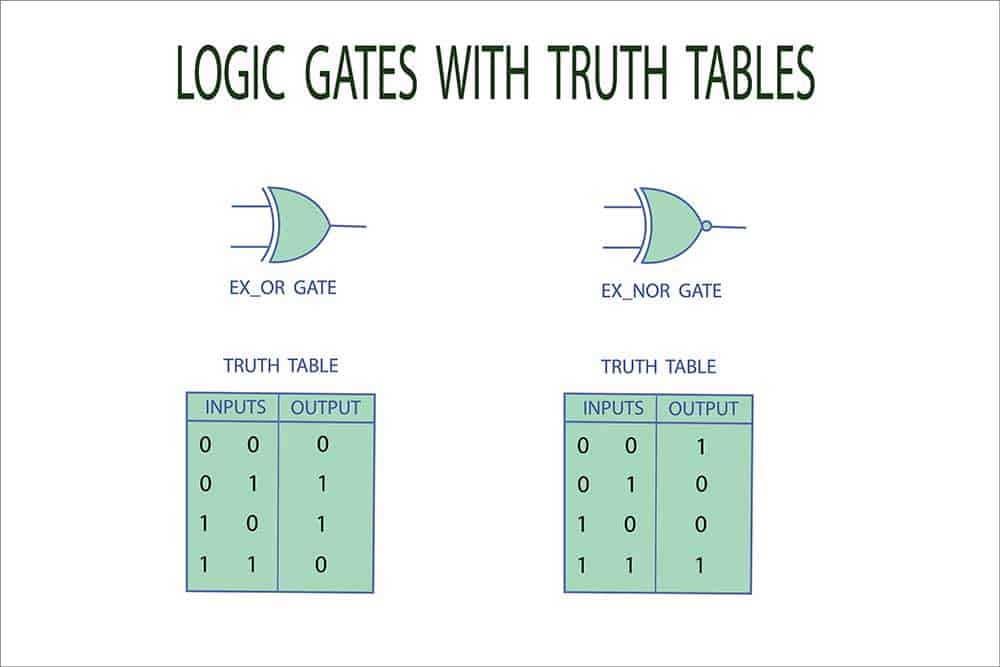
Exclusive logic gates with their truth tables
XOR Gate
The term “XOR (exclusive or)” implies the logical operator “or” is ambiguous when both inputs are true.
And it functions like an “either-or” statement, meaning the output is true if either input is true, but not both. If both inputs are true, the result is false.
An easier way to understand this logical operation is that the output is false if the inputs are the same.
But if different, the output is true. The boolean function for this operation is Y(Output)=A’.B+A.B’.
| Input (A and B) | Y(Output) | |
| 0 | 0 | 0 |
| 0 | 1 | 1 |
| 1 | 0 | 1 |
| 1 | 1 | 0 |
XNOR Gate
XNOR is an XOR gate followed by an inverter (NOT) gate.
So it gives a true output if both inputs are the same (low or high) and a false result if one input is high. Its boolean function is Y(Output) = A.B+A’B’.
| Input (A and B) | Y(Output) | |
| 0 | 0 | 1 |
| 0 | 1 | 0 |
| 1 | 0 | 0 |
| 1 | 1 | 1 |
What About Three-State Logic Gates?
The logic gates we’ve looked at above can only output two logic outputs: high or low (true or false). But 3-state logic gates have an additional result known as high impedance.
This output is not binary, so it plays no role in the logic operations. But it can help give control over a signal line.
For instance, high can imply positive voltage, low can mean negative voltage, and high impedance indicates if you have an output disconnected from the circuit.
Combinational vs. Sequential Digital Logic Circuit
You can combine the logic gates described above to form combinational or sequential circuits, as shown below.
Combinational Digital Logic Circuit
These circuits perform switching operations using a combination of basic (AND, OR, and NOT) and universal gates (NAND and NOR).
And the output from these combinational logic circuits at any time depends on the current input. So they don’t have memory components.
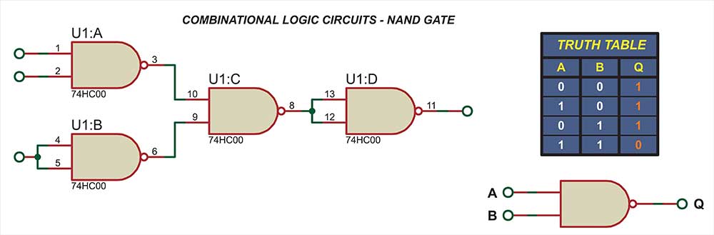
A combinational logic circuit diagram using NAND gates
Some examples are encoders, decoders, half adders, full adders, code converters, multiplexers, and de-multiplexers.
These combinational circuits fall into these three primary categories.
- Arithmetic and Logical Operators: adders (half and full), programmable logic devices, subtractors, and comparators.
- Code Converters: binary coded decimal, binary, and 7-segment converters.
- Data Transmission: multiplexer, demultiplexer, encoder, and decoder.
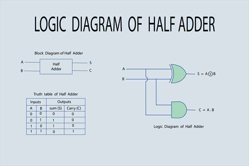
A logic circuit diagram of a half adder
Sequential Digital Logic Circuit
A sequential digital logic circuit consists of a combinational circuit with memory devices to store previous outputs.
So the circuit’s output depends on current and past inputs from memory, and you can design it using a finite-state machine.
The combinational circuit part of the system takes in two current inputs plus outputs from the memory devices.
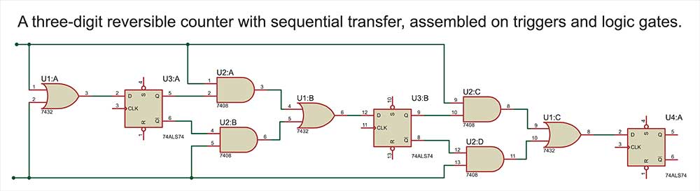
A sequential digital logic circuit for a 3-digit reversible counter
Internal inputs and outputs from the combinational circuit form a portion of the secondary devices, where the inputs to these devices are storage element state variables.
But secondary digital device outputs are excitations for storage elements.
Examples of sequential digital logic circuits include flip-flops and counters.
These digital logic circuits can be clock, event, or pulse driven.
- Clock Driven: these sequential logic circuits are synchronous because the output state transition only occurs if the input signal gets applied with clock pulses.
- Event Driven: these circuits are asynchronous because the output state transition does not depend on a clock input (depends on an input pulse)
- Pulse Driven: a combination of clock and event-driven circuits to respond to the triggering input and clock pulses
Wrap Up
The complex digital circuitry that makes computers function begins with designing digital logic circuits.
And the hardware behind these logical operations is primarily transistors.
Connecting and joining these pieces eventually creates complex logic functions that constitute advanced digital electronics.
We hope this article has been insightful. Comment below to keep the conversation going.
Special Offer: $1 for 5 PCB Assemblies!
Please email [email protected] for details.