
The automatic day night light switch is an advanced technology that has been in use for decades. They work through an automatic day-night light switch circuit and provide better visibility on the places they illuminate. Often, they will provide lighting control for the exterior lights automatically at nighttime without your effort. For instance, the automated lighting system in the streets, the corridor light controller, or the outdoor lights with a dawn light sensor.
The content we will narrow on today gives four different insightful ways which you can use to construct an automatic lamp circuit.
Automatic Day Night Light Switch
Before we begin, note this: you can apply all four DIYs to control a max load, i.e., an AC mains lamp with 220V as the input power. Furthermore, the control results from the response level of varying degrees of ambient light surrounding the environment. Also, any regular light bulb will contain energy-saving sensors.
The DIY circuits with automatic switching include:
Project using a transistor to make light-activated day night switch
Parts list/ Product description based on components
- C1 – 470uF/25v
- C2 – 10uF/ 25v
- R1, R3, R2 – 4k7 ¼ W
- All diodes at 1N4007
- Transformer – 0 to 12v per 500mA or 1 amp
- T1, T2 – BC547
- VR1 – 10k preset
- Relay at 12v, 5 amp, 400 ohms
- LDR – an LDR with approx. 10k – 50k daylight distance will do
Circuit diagram design
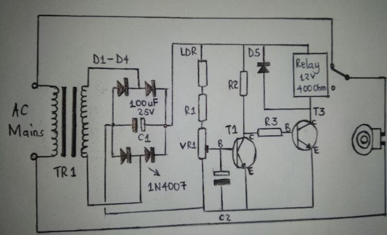
Circuit description
The circuit diagram above uses transistors and other electronic components such as Ike resistors in the DIY construction.
- First, transistors act as inverters; switching OFF T2 automatically switches ON T2 and vice versa. Besides the transistors, light/ connected load and relay also follow the same principle.
- Then, T1 operates as a comparator and comprises an LDR crossway at its base. Also, it connects the +ve supply through a preset.
- Further, LDR senses the condition of the surrounding ambient light and then triggers T1 when the ambient light level surpasses the specific threshold. A preset P1 always sets the point.
- The importance of the two transistors is that they help level down the circuit’s hysteresis. Sometimes, a single transistor can be hugely affected by hysteresis.
Project of an automatic night-operated LED lamp circuit.
With this second circuit, you will need new LED flashlights with high efficiency and brightness. Ultimately, you will have made a similar electronic device with outstanding new features.
Parts list
| Components | Quantity |
| PNP BC557A | 1 |
| Battery 3V coin | 1 |
| 1K resistor | 1 |
| Compatible phototransistor | 1 |
| Super bright white LED | 1 |
Circuit description and working
We use a phototransistor to ensure the circuit’s operation after dark. In that way, the LED will be switched ON when there’s no daylight. Further on, a button battery type keeps the circuit compact, much like in devices such as watches and calculators.
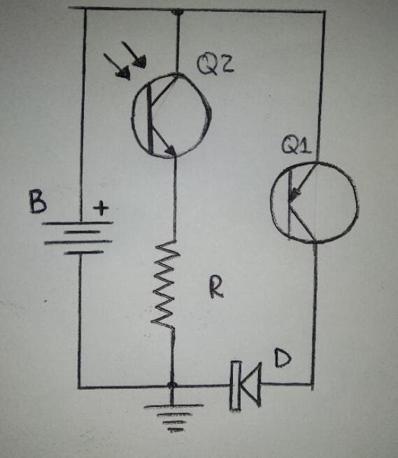
Comprehending the diagram
During the day, the ambient light will illuminate the phototransistor. Subsequently, the lead of the emitter’s voltage becomes sufficiently high for the PNP transistor’s base, making it stay shut.

An indication of a photodiode/phototransistor in a circuit.
When it becomes dark, the phototransistor will lose its conduction, thus reducing the voltage at the emitter. Therefore, the phototransistor switches OFF.
Then, Q1, through its ground/base resistor R, starts receiving the biasing. And as the darkness continues, Q1 will gradually illuminate more brightly.
Equally important, you can vary the values of resistor R to achieve a desirable control level of the ambient light that you require to switch ON the LED. Note:
If you are thinking of using a potentiometer, do not since it may interfere with the dimensions and compactness of the DIY unit.
Secondly, the automatic night-operated LED lamp circuit may require approx. 13mA during the LED’s illumination and some 100 uA when the LED is switched off. A current rating of 10A will also come in handy.
Project using CMOS NAND gates to make a light-activated day dark switch
You will use CMOS integrated circuits to achieve the function of a light-activated day-dark button. In addition, you will use an IC 4093 – a quad 2-input NAND gate IC.
Parts list
- Relay – 400 ohms, 5 amp, and 12V
- D1 – 1N4007
- P1 – 1M preset
- R1 – LDR with approx. 10k to 50k resistance in daylight
- C1 – 0.1uF ceramic disc
- T1 – BC547
- R2 – 10k ¼ W
- IC – IC 4093 or IC 4049
Circuit description
- At first, shorting the inputs together, tune each gate into inverters. Subsequently, the gates’ input logic level is effectively reversible at the outputs.
- Moreover, opt for three NAND gates instead of one for the best results.
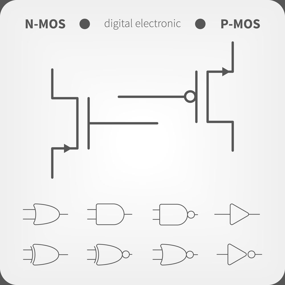
A symbol of NAND gates.
- Also, the variable resistor sets the gate’s triggering point when the light fall intensity on the LDR reaches a desirable level.
- Afterward, the gate input will be higher, and the output will reduce, contributing to a rise in the buffer gates’ production.
- Eventually, the relay assembly and transistor get triggered, and the connected load lights up as intended.
Applications of Automatic Day Night Light Switch
The switch circuit has got a wide range of applications, such as:
- Doorway lighting/outdoor lighting,
- In shops,
- Garden lighting,
- Hoardings,
- Security lights,
- Passage lighting, and
- Street lighting.
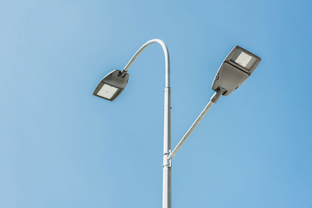
Street lights automatically turn on in the dark.
FAQs on automatic Day Night Light Switch
Question 1: I need clarification on the circuit diagram in the second DIY, i.e., the Automatic Night Operated LED lamp circuit. Usually, I build PNP circuits with the collector on the positive and emitter plus load to the ground. In this case, however, the Q1 emitter connects to +ve, and the collector connects to the ground and freight. Why is that?
Answer: Using a DC instead of an AC power source is, in fact, pretty simple. Often, all you need to do is remove the relay and place the LEDs in their stead. Then, depending on the LED’s specification, you will gauge the configuration driver transistor rating and LEDs.
Summary
To summarize the article, we hope the information we have given you on automatic -night light switches will help your project. We are still open to more questions, don’t hesitate to contact us.